1PH822x-1Ax10-xxx1-Z, Z=L03
1PH822x-1Ex00-xxx1-Z, Z=L03
1PH822x-1Ex10-xxx1-Z, Z=L03
1PH822x-1Hx00-xxx1-Z, Z=L03
1PH822x-1Hx10-xxx1-Z, Z=L03
1PH822x-1Jx00-xxx1-Z, Z=L03
1PH822x-1Jx10-xxx1-Z, Z=L03
1PH822x-1Mx00-xxx1-Z, Z=L03
1PH822x-1Mx10-xxx1-Z, Z=L03
1PH822x-2Ex00-xxx1-Z, Z=L03
1PH822x-2Ex10-xxx1-Z, Z=L03
1PH822x-2Mx00-xxx1-Z, Z=L03
1PH822x-2Mx10-xxx1-Z, Z=L03
Operating conditions of shaft heights 180 and 225
The vibration load that is permissible by default for the 1PH8 main motors is described in Chapter
"Vibration response." Take the maximum permissible vibration acceleration rates in conjunction
with option L03 from the following table:
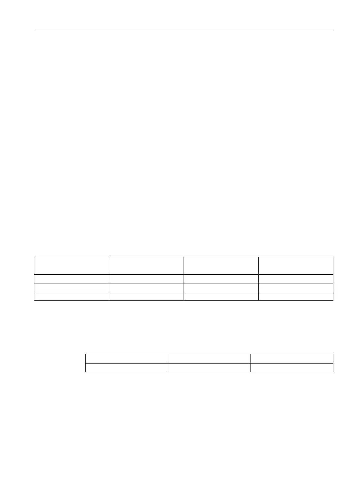
Table 5-14 Maximum permissible vibration accelerations
Standard
SH 180 and SH 225
Option L03
SH 180
Option L03
SH 225
Vertical 1.0g 4.0g 3.5g
Horizontal 1.0g 3.5g 3.2g
Axial 1.0g 3.5g 3.2g
Vibration acceleration rates (0peak) in the frequency range from 0Hz to 1kHz at the
bearings must not exceed the values listed in the table. The position of the measuring points
is dened in ISO10816-1. The customer must pin the 1PH8 motor at the DE and NDE using
a cylindrical grooved pin according to ISO 8740. To do this, place the motor down on a metal
foundation. For easier removal, do not use blind holes in the foundation for the pinning.
Recommendation: Through holes for pressing through the cylindrical grooved pins.
Grooved pins acc. to ISO 8740 SH 180 SH 225
Grooved pin diameter 5mm 6mm
Measures included
• Reinforced version of a DE bearing shield
• Fan unit (EC fan) with upgraded electronic components
• Screws locked with Loctite 270
Motor components and options
5.2Options
1PH8 SIMOTICS M main motors
Conguration Manual, 12/2022, A5E51895839A 179

 Loading...


