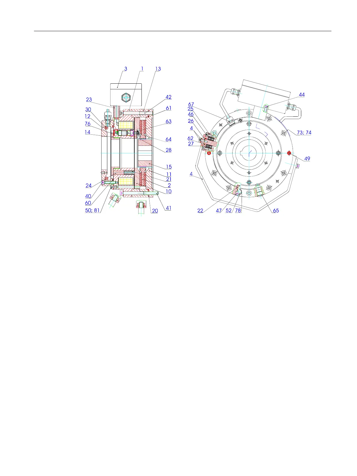
Design, method of operation and construction features
1 Coil form with coil 40 Screw for tacho ange
2 Friction disk with friction lining 41 Fixing screw
3 Terminal box, complete 42 Cylinder head screw
4 Manual brake release, complete 46 Fixing screw for manual release cover
10 Armature disk 47 Screw for sliding block
11 Brake ange 49 Emergency release screw
12 Tacho ange 50 Screw plug for emergency release
13 Socket 52 Screw for blockable manual release
14 Adjustment ring 60 O-ring for tacho
15 Pinion 61 O-ring for brake ange
20 Shim 63 Lock nut for microswitch
21 Compression springs 64 Grub screw (microswitch)
22 Sliding block 65 Screw plug for air gap measurement
23 Spacer for terminal box 67 Screw connection
24 Spring bolt 73 Rating plate
25 Manual release cover 74 Pin (rating plate mounting)
26 Eccentric bolt 76 Adhesive
27 Deep-groove ball bearing 78 Washer for item 52
28 Microswitch 81 Sealing ring for item 50
Figure5-9 Mounting of holding brake SH 180 and SH 225
The NFF brake is a spring-loaded electromagnetic twin-disk brake that brakes in the de-
energized state and releases electromagnetically.
Motor components and options
5.2Options
1PH8 SIMOTICS M main motors
Conguration Manual, 12/2022, A5E51895839A 195

 Loading...


