Terminal box connection
The type designation of the mounted terminal box as well as the details on the power
connection for the line supply cables can be taken from the following table. A circuit diagram to
connect the motor winding is provided in the terminal box when the motors are shipped.
ෙ
<FRQQHFWLRQ
IRU6+WR
IRU6+DQG
VXSSO\YROWDJH9
FRQQHFWLRQ
VXSSO\YROWDJH99
0RWRU
0RWRU
7HUPLQDOER[
7HUPLQDOER[
RQO\IRU6+DQG
89:
89:
89:
89:
Figure9-5 Circuit diagram
Note
Connecting temperature sensors and PTC thermistors
The spare temperature sensor (option A25 for shaft heights 80 to 160, standard from shaft
height 180 and higher) and the PTC thermistor circuit for alarm/trip (option A12) are connected
to a signal terminal block in the terminal box.
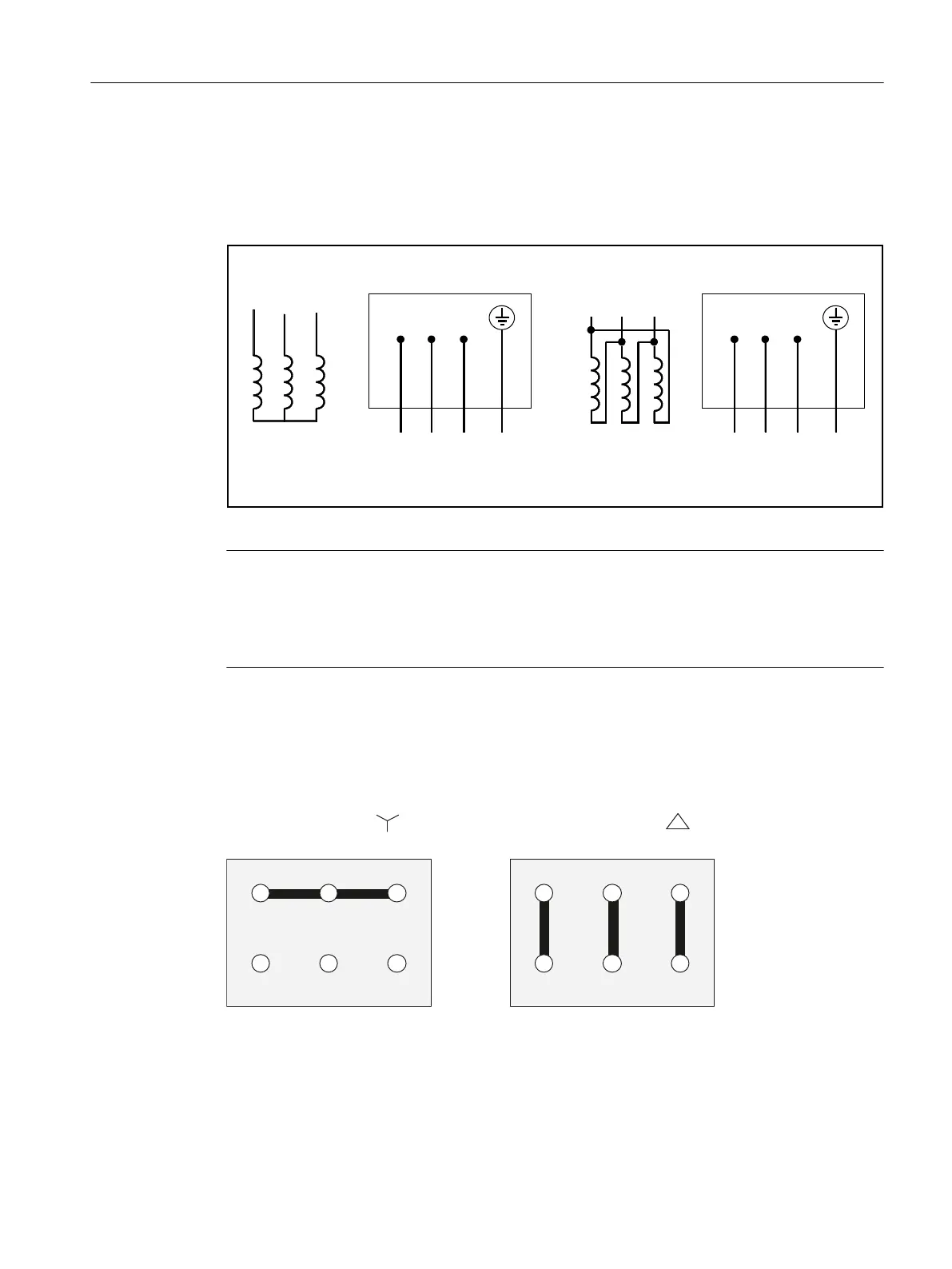
Star/delta connection in the terminal box (SH80 to SH160)
The star/delta connection can be implemented using an external contactor circuit or as
permanent setting in the terminal box.
:89
89:
6WDUFRQQHFWLRQ'HOWDFRQQHFWLRQ
:89
89:
6WDQGDUG
Figure9-6 Fixed star/delta connection in the terminal box
Electrical connection
9.3System integration
1PH8 SIMOTICS M main motors
Conguration Manual, 12/2022, A5E51895839A 229

 Loading...


