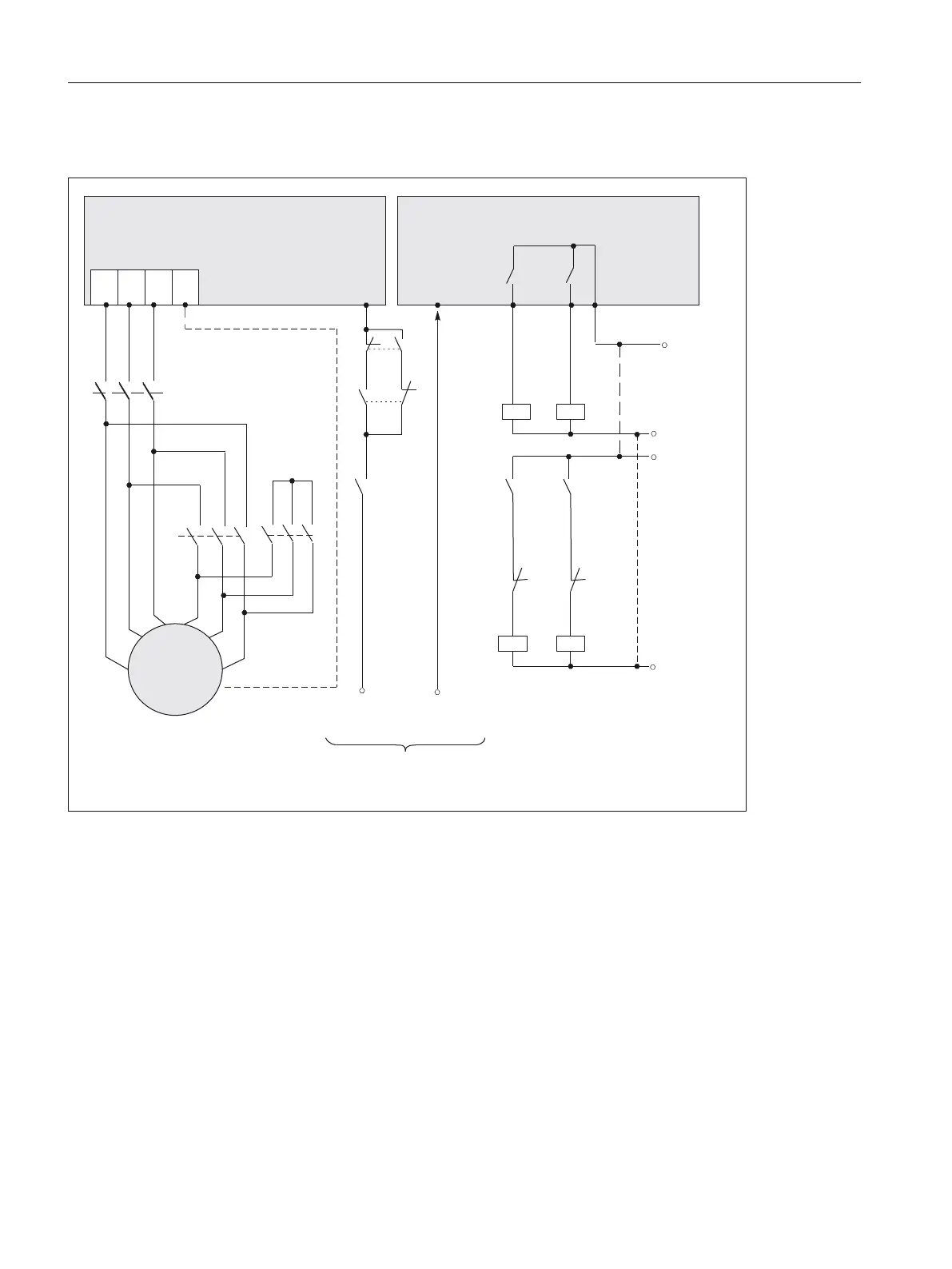
Connection diagram for Y/D changeover
3/&RXWSXWV
$X[LOLDU\FRQWDFWRU
SRZHUVXSSO\PD[
9'&
IURPWKH1&3/&
(QDEOHSXOVHV
<˂FKDQJHRYHU
0RWRU0RGXOH
6,1$0,&66
&RQWURO8QLW','2[[
%L&RVRXUFH
%,S U;;
.K
.K
.
.
.
.
.K
.K
.
.
8
:
:
8
.
.
98
89
:
3(
:
9
9
˂
<
6,180(5,.'
<˂
.
[
.
[
$;=$;<(;<
Figure9-23 Connection diagram for Y/D changeover with SINAMICS
1)
Safe operating stop cannot be guaranteed by simply opening K1 and K2. Therefore, for
safety reasons there should be electrical isolation provided by contactor K
x
. This contactor
may only be switched-in the no-current condition, i.e. the pulse enable must be withdrawn
40 ms before the contactor is opened (de-energized).
2)
Terminal X3 of the voltage limiting module VPM should be wired to a digital input of the
Control Unit on which the assigned 1PH8 motor spindle is also controlled. For the case that
several VPMs are used, each terminal must be wired to a separate digital input of the
relevant Control Unit.
If an armature short-circuit occurs (terminal X3 has opened), the pulses of the relevant axis
must be inhibited. To achieve this, the digital input used is interconnected to the control bit
OFF2 (pulse inhibit) via p0845 = r0722.XX.
Further information can be found in the SINAMICS S120 Function Manual.
Electrical connection
9.3System integration
1PH8 SIMOTICS M main motors
242 Conguration Manual, 12/2022, A5E51895839A

 Loading...


