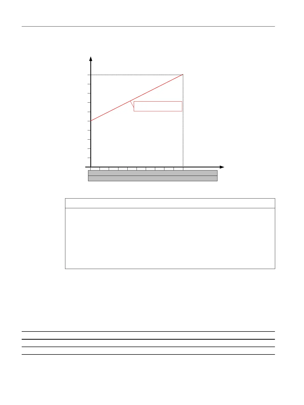
Diagram of control via an external setting signal
5DWHGVSHHG
6HWSRLQWVLJQDO9
3:0
nM
1 2
3
4 5
6 7 8
9
10
80
70
60
50
40
30
20
10
0...10 V
10 20
30
40 50
60 70 80 90
100
0...100 % PWM
0
0
90
100 %
n
min
= 50 % n
max
= 100 %
NOTICE
Removing the factory-mounted jumper
The 1PH8 motor can overheat if the external EC fan is operated at low fan speeds as a result of
the setpoint signal it receives.
• Monitor the motor using the integrated temperature sensors.
• Integrate the temperature monitoring into the interlocking circuit.
If the company operating the plant or system removes the jumper (which was inserted in
the factory), that company becomes responsible for the functional safety of the drive,
especially if the safety instructions are not complied with.
Line connection: Fuse protection
The EC external fans have integrated overload protection, making an external motor
protection device (e.g. motor circuit breaker) unnecessary. A simple conductor protection
is sucient.
Simple conductor protection with a fuse or MCB:
Fuse MCB Conductor cross section Conductor cross section
VDE UL VDE mm
2
*AWG
16A 15A C16A 1.5 16
(* AWG = American Wire Gauge)
Electrical connection
9.3System integration
1PH8 SIMOTICS M main motors
252 Conguration Manual, 12/2022, A5E51895839A

 Loading...


