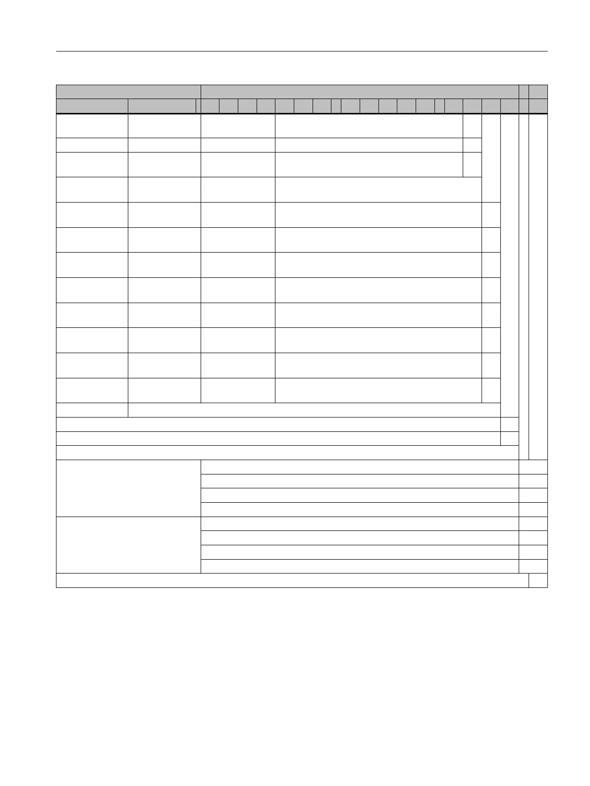
Descriptions Data position of the order No.
1 2 3 4 5 6 7 - 8 9 10 11 12 - 13 14 15 16 - Z
Siemens/EN
60034-14
ange accuracy
Standard A N A
Advanced Life‐
time
A N P
Power connec‐
tion
6)
Cable entry Signal connec‐
tion
(looking onto DE)
Terminal box
(top)
Right DE A
Terminal box
(top)
Left DE B
Terminal box
(top)
NDE Left C
Terminal box
(top)
10)
DE Left D
Power connec‐
tor (top)
3) 7)
Right DE E
Power connec‐
tor (top)
3) 7)
Left DE F
Power connec‐
tor (top)
3) 7)
NDE Left G
Power connec‐
tor (top)
3) 7)
DE Left H
Version
Without a DRIVE-CLiQ interface, PT1000 temperature sensor in the stator winding 2
With a DRIVE-CLiQ interface 1
Brake versions:
Brake supply voltage
230 V 1 AC, 50/60 Hz
Holding brake DE U60
Holding brake DE with microswitch U61
Holding brake DE with manual brake release lever U62
Holding brake DE with microswitch and manual brake release lever U63
Brake supply voltage
24 V DC
Holding brake DE U65
Holding brake DE with microswitch U66
Holding brake DE with manual brake release lever U67
Holding brake DE with microswitch and manual brake release lever U68
Z options that cannot be combined with holding brake DE: K18, V91, M03, M39
1) A U option must also be stated in the order to specify the holding brake version.
Shaft height 80: limited to n
max
= 5000r/min
Shaft height 100: limited to n
max
= 5000r/min
Shaft height 132: limited to n
max
= 4500r/min
Shaft height 160: limited to n
max
= 4000r/min
2) Only possible if 8th data position is "3" (induction version)
4) With holding brake, degree of protection is limited to IP55.
5) Not possible with shaft height 160.
Motor description
3.4Selection and ordering data
1PH8 SIMOTICS M main motors
Conguration Manual, 12/2022, A5E51895839A 51

 Loading...


