The values specied in the table below apply to the same conditions as are described above
for bearing change intervals:
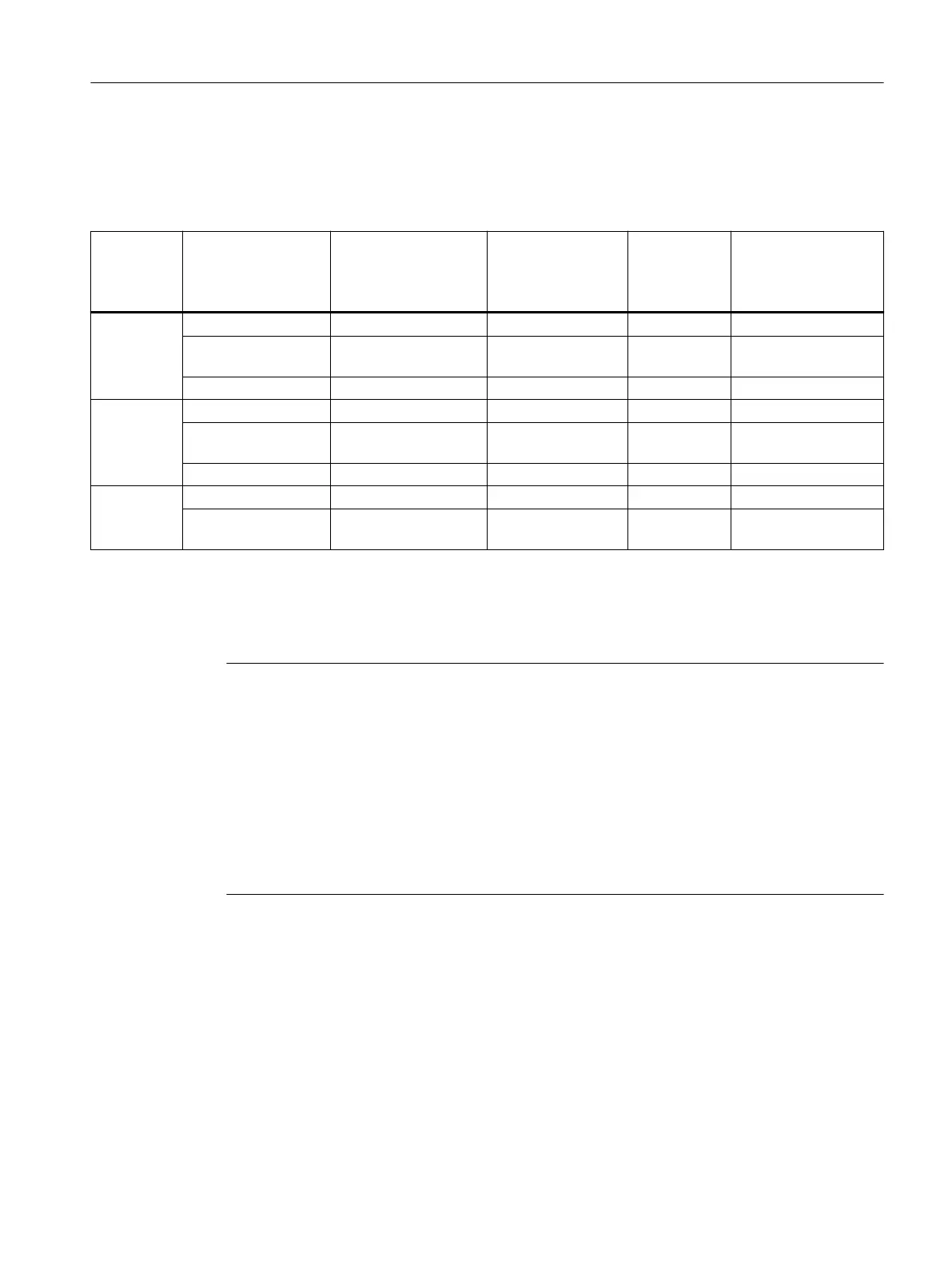
Table 4-19 Relubrication intervals
Shaft
height
Bearing version Relubrication inter‐
val in operating
hours
4)
h
Quantity of grease
for each relubrica‐
tion operation
1)
g
Grease cham‐
ber
2)
g
Possible number of
relubrication inter‐
vals
3)
180 Standard 7000 15 80 5
Increased radial
forces
4000 20 80 4
Performance 4000 15 80 5
225 Standard 7000 30 180 6
Increased radial
forces
4000 40 180 4
Performance 4000 30 180 6
280 Standard 7000 40 400 10
Increased radial
forces
4000 50 400 8
1)
Grease quantity for relubrication for normal conditions (ambient temperature up to 40°C, horizontal mounting.
2)
Holding capacity of the grease chamber with precise adherence to the grease quantity for each relubrication interval.
3)
Calculated number of re-lubricating intervals; the bearing lifetime is specied statistically by means of the L
10h
denition.
4)
Relubricating intervals must be halved for vertically mounted units.
Note
Adapting relubricating intervals
Unfavorable factors such as the eects of mounting/installation, speed or mechanical loads
require that the relubricating intervals are appropriately adapted. Situations such as these
require special consideration or must be calculated - and must be engineered according to the
limitations and constraints together with the responsible motor plant.
The increased axial loads imposed on the bearings on vertically mounted motors can reduce the
bearing lifetime by almost 50%. This applies to shaft heights 180 to 280 due to the rotor weights.
A check which takes into account the relevant boundary conditions must be performed on SH
280 in the relevant motor factory.
Mechanical properties
4.4Types of bearing
1PH8 SIMOTICS M main motors
Conguration Manual, 12/2022, A5E51895839A 93
 Loading...


