Programming and Operating Manual (Milling)
142 6FC5398-4DP10-0BA6, 09/2017
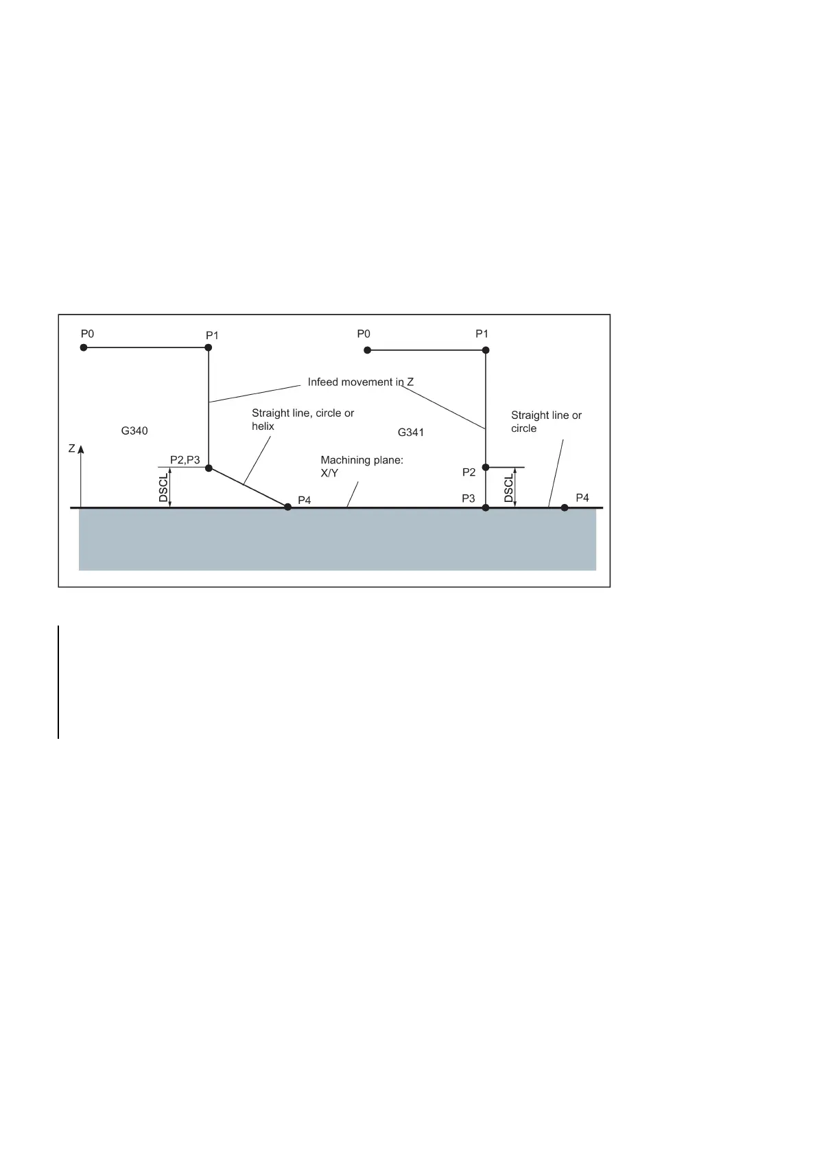
Controlling the infeed motion using DISCL and G340, G341
DISCL=... specifies the distance of point P2 from the machining plane (see following figure).
In the case DISCL=0, the following will apply:
● With G340: The whole approach motion consists only of two blocks (P1, P2 and P3 are identical). The approach contour
is generated from P3 to P4.
● With G341: The whole approach motion consists only of three blocks (P2 and P3 are identical). If P0 and P4 are located
in the same plane, only two blocks will result (there will be no infeed motion from P1 to P3).
It is monitored that the point defined by DISCL lies between P1 and P3, i.e. with all motions that possess a component which
runs vertically to the machining plane, this component must have the same sign. If a reversal of the direction is detected, a
tolerance of 0.01 mm is permitted.
See the following sequence of the approach motion dependent on G340/G341 (example with G17):
Programming example: Approach along a semi-circle with infeed
; Activate tool, X/Y plane
N30 G41 G34 7 G340 DISCL=3 DISR=13 Z=0 F5 00
; Approach along a semi-circle with radius: 13 m m,
; Safety clearance to the plane: 3 mm
alternatively N30/N40:
N30 G41 G34 7 G340 DISCL=3 DISR=13 X40 Y-10 Z0 F5 00
or
N30 G41 G347 G340 DISCL=3 DISR=13 F500
N40 G1 X40 Y-10 Z0
Explanation with regard to N30/N40:
By using G0 (from N20), the point P1 (starting point of the semi-circle, corrected by the tool radius) is approached in the
plane Z=30, then lowering to the depth (P2, P3) with Z=3 (DISCL). The contour is reached at point X40 Y-10 in the depth
Z=0 (P4) along a helix curve at a feedrate of 500 mm/min.
Approach and retraction velocities
● Velocity of the previous block (e.g. G0):
All motions from P0 up to P2 are executed at this speed, i.e. the motion parallel to the machining plane and the part of
the infeed motion up to the safety clearance DISCL.
● Programmed feedrate F:

 Loading...


