Programming and Operating Manual (Milling)
80 6FC5398-4DP10-0BA6, 09/2017
● Incremental dimension, X=IC(value) only this value applies exclusively for the stated axis and is not influenced by
G90/G91. This is possible for all axes and also for SPOS, SPOSA spindle positionings, and interpolation parameters I, J,
K.
● Inch dimension, G70 applies for all linear axes in the block, until revoked by G71 in a following block.
● Metric dimension, G71 applies for all linear axes in the block, until revoked by G70 in a following block.
● Inch dimension as G70, however, G700 applies also for feedrate and length-related setting data.
● Metric dimension as G71, however, G710 applies also for feedrate and length-related setting data.
● Diameter programming, DIAMON on
● Diameter programming, DIAMOF off
Diameter programming, DIAM90 for traversing blocks with G90. Radius programming for traversing blocks with G91.
Plane selection: G17 to G19
Fu n ctionality
To assign, for example,
tool radius and tool length compensations
, a plane with two axes is selected from the three axes X,
Y and Z. In this plane, you can activate a tool radius compensation.
For drill and cutter, the length compensation (length1) is assigned to the axis standing vertically on the selected plane. It is
also possible to use a 3-dimensional length compensation for special cases.
Another influence of plane selection is described with the appropriate functions (e.g. Section "Support for the contour
definition programming").
The individual planes are also used to define the
direction of rotation of the circle for the circular interpolation
CW or CCW.
In the plane in which the circle is traversed, the abscissa and the ordinate are designed and thus also the direction of
rotation of the circle. Circles can also be traversed in a plane other than that of the currently active G17 to G19 plane (For
more information, see Section "Circular interpolation (Page 93)".).
The following plane and axis assignments are possible:
Plane (abscissa/ordinate)
Vertical axis on plane
(length compensation axis when drilling/milling)
X/Y Z
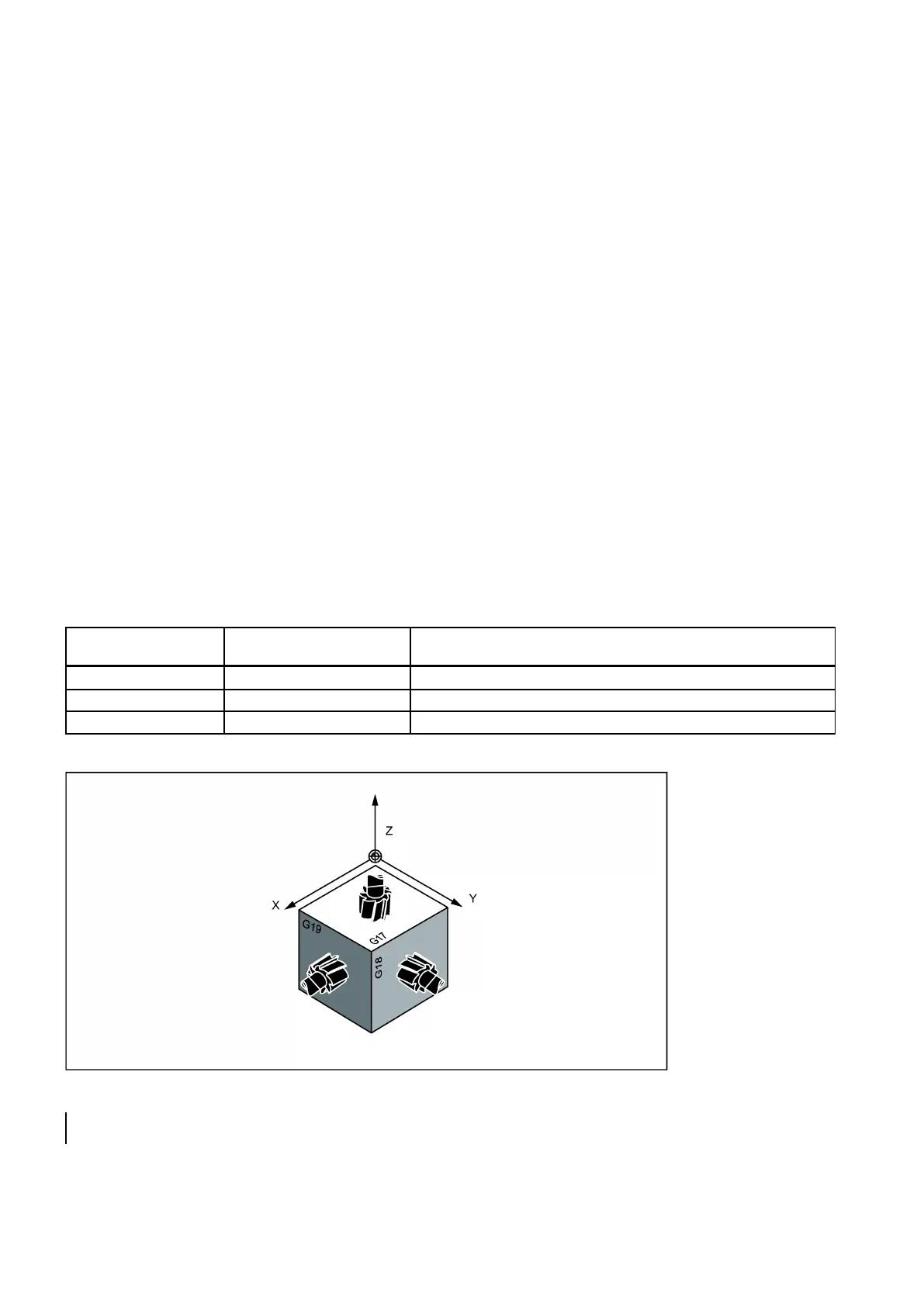
See the following illustration for planes and axes when drilling/milling:
; tool length compensation (length1) i n Z axis