Programming and Operating Manual (Milling)
6FC5398-4DP10-0BA6, 09/2017
165
VRT (variable retraction value for chip breakage with VARI=0)
You can program the retraction path for chip breaking.
DTD (dwell time at final drilling depth)
The dwell time at final drilling depth can be entered in seconds or revolutions.
DIS1 (programmable limit distance for VARI=1)
The limit distance after re-insertion in the hole can be programmed.
The limit distance is calculated within the cycle as follows:
● Up to a drilling depth of 30 mm, the value is set to 0.6 mm.
● For larger drilling depths, the limit distance is the result of
(RFP + SDIS - current depth) / 50. If this calculated value >7, a limit of 7 mm, maximum, is applied.
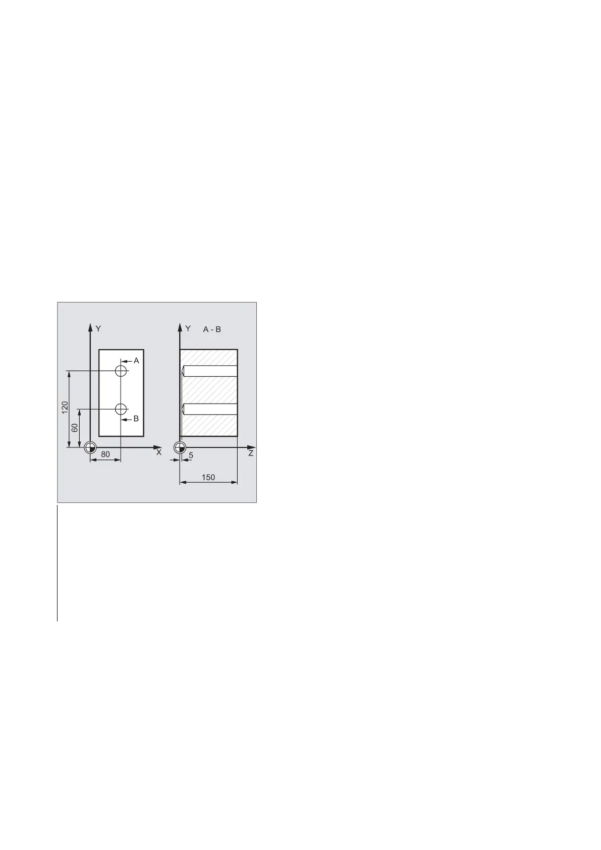
Programming example 1: Deep-hole drilling
This program executes the cycle CYCLE83 at the positions X80 Y120 and X80 Y60 in the XY plane. The first drill hole is
drilled with a dwell time zero and machining type chip breaking. The final drilling depth and the first drilling depth are entered
as absolute values. In the second cycle call, a dwell time of 1 s is programmed. Machining type chip removal is selected, the
final drilling depth is relative to the reference plane. The drilling axis in both cases is the Z axis.
N10 G0 G17 G90 F50 S500 M4
; Specification of technology values
; Approach retraction plane
; Approach first drilling position
N50 CYCLE83(20,0,3,-15,,-6,,1,1,1 ,1,0,3,4,3,1,2)
; Call of cycle; depth parameters with
absolute values
; Approa ch next drilling position
N70 CYCLE83(20,0,3,-15,,-6,,1,1,1 ,1,0,3,4,3,1,2)
; Cycle call with relative data for fi nal
drilling depth and first drilling dept h;
the safety clearance is 1 mm and the

 Loading...


