Programming and Operating Manual (Milling)
6FC5398-4DP10-0BA6, 09/2017
203
Using the CDIR parameter, the milling direction can be programmed directly with "2 for G2" and "3 for G3", or alternatively
with "synchronous milling" or "conventional milling".
Down-cut and up-cut milling are determined internally in the cycle via the direction of rotation of the spindle activated prior to
calling the cycle.
Use the parameter VARI to define the machining type.
Possible values are:
● 1=roughing
● 2=finishing
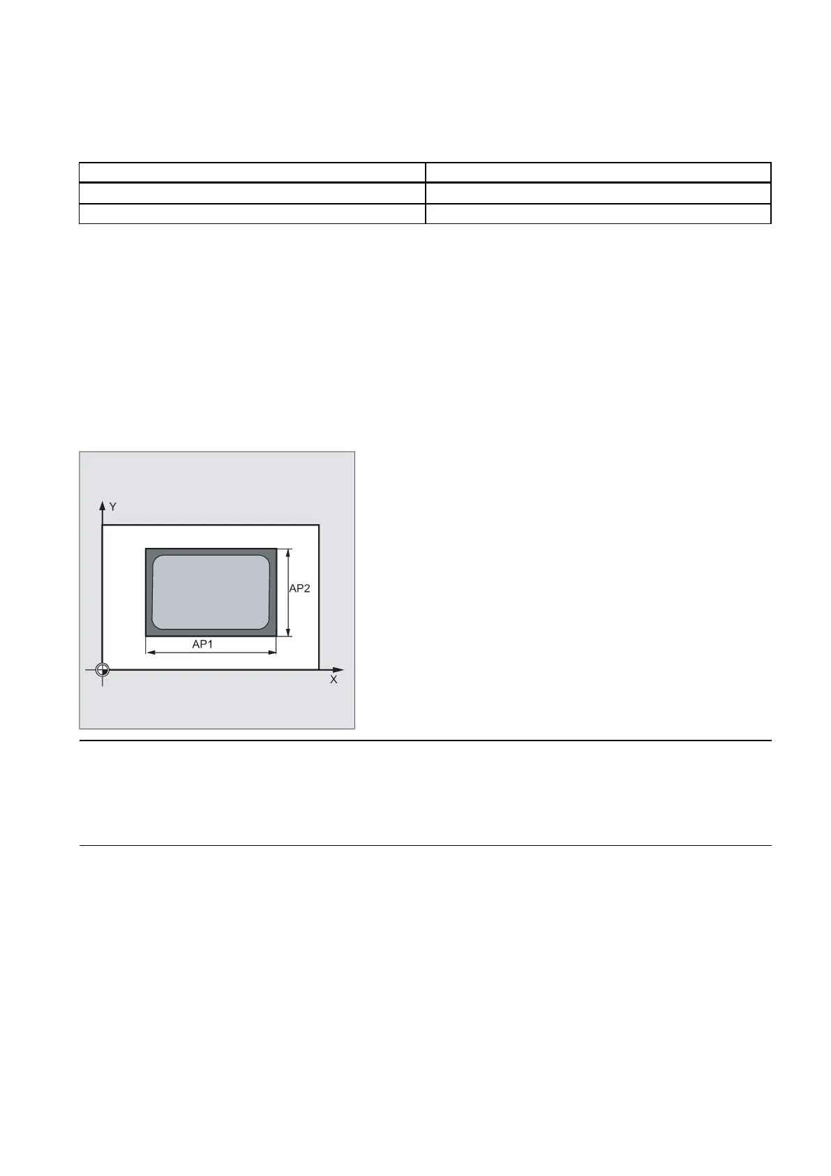
AP1, AP2 (blank dimensions)
When machining the spigot, it is possible to take into account blank dimensions (e.g. when machining precast parts).
The basic sizes for the length and width (AP1 and AP2) are programmed without sign and their symmetrical positions
around the spigot center are computed in the cycle. The internally calculated radius of the approach semi-circle depends on
this dimension.
A tool compensation must be programmed before the cycle is called. Otherwise, the cycle is canceled and alarm 61009
"Active tool number=0" is output.
Internally in the cycle, a new current workpiece coordinate system is used which influences the actual value display. The
zero point of this coordinate system is to be found in the pocket center point.
At the end of the cycle, the original coordinate system is active again.

 Loading...


