Programming and Operating Manual (Milling)
312 6FC5398-4DP10-0BA6, 09/2017
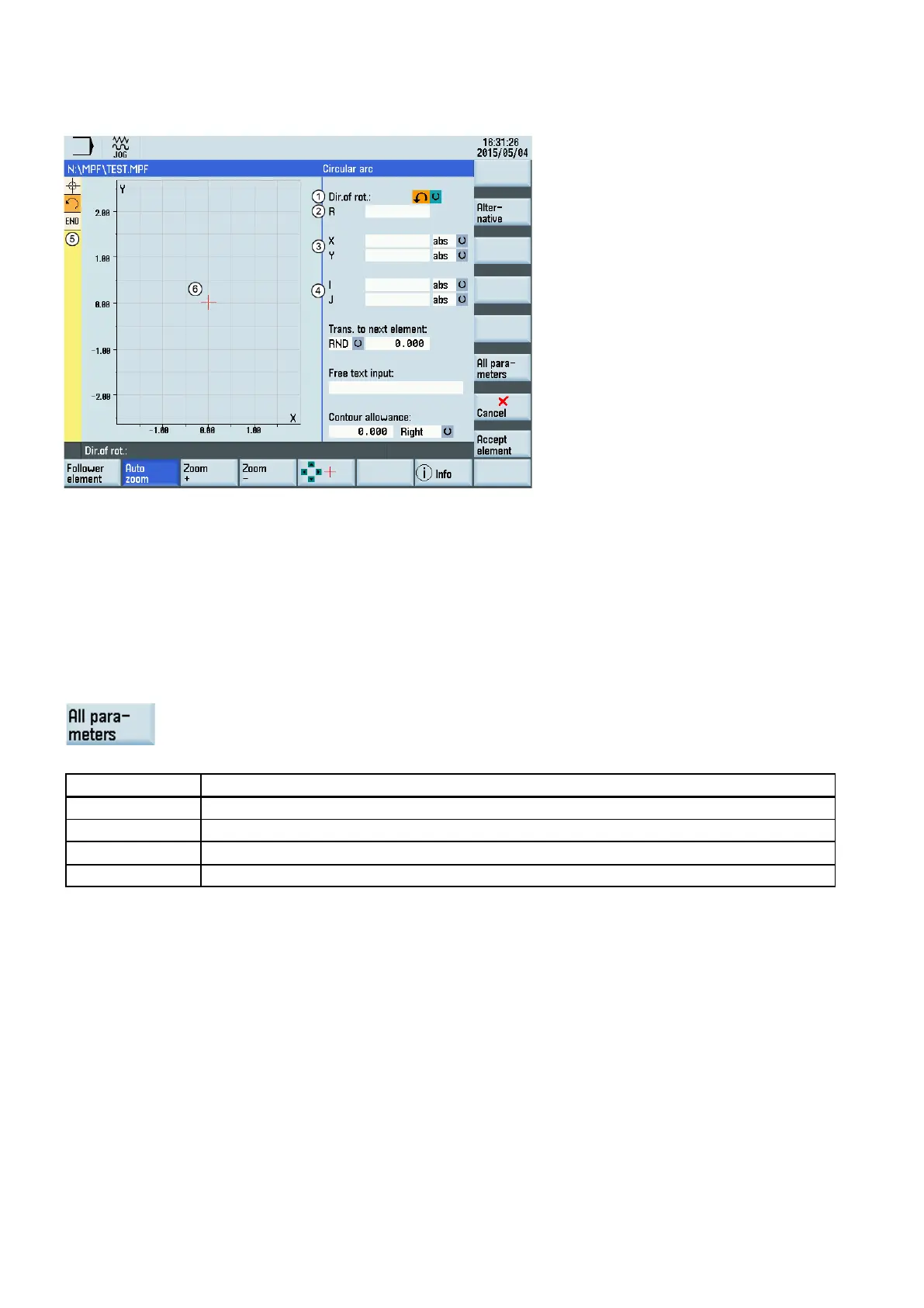
Parameters for programming circular arcs
Direction of rotation of the circular arc: clockwise or counter
-clockwise
Absolute (abs)/incremental (inc) end positions in X and Y directions
Absolute (abs)/incremental (inc) positions of circle cen
ter point in Y (I) and X (K) directions
The contour chain which displays the start point and programmed contour elements. The current position in the chain
is color-highlighted.
The graphics window which displays the progress of the contour as you configure the parameters for the contour ele-
ments.
e following additional parameters are displayed after you press this softkey:
Starting angle with reference to Y axis
Angle to preceding element; tangential transition: α2=0
End angle with reference to Y axis
β2 Angle of aperture of circle
The names of the identifiers (X or Y ...) are defined in the machine data where they can also be changed.
Transition to next element
A transition element can be used whenever there is a point of intersection between two neighboring elements; this can be
calculated from the input values.
You can choose to insert either a radius (RND), a chamfer (CHR) or an undercut as the transition element between any two
contour elements. The transition is always appended to the end of a contour element. You select transition elements in the
parameter input screen for the relevant contour element.
Radius or chamfer at the start or the end of a turning contour:
In simple turning contours a chamfer or radius must often be appended at the start and end of the contour.

 Loading...


