Programming and Operating Manual (Milling)
6FC5398-4DP10-0BA6, 09/2017
55
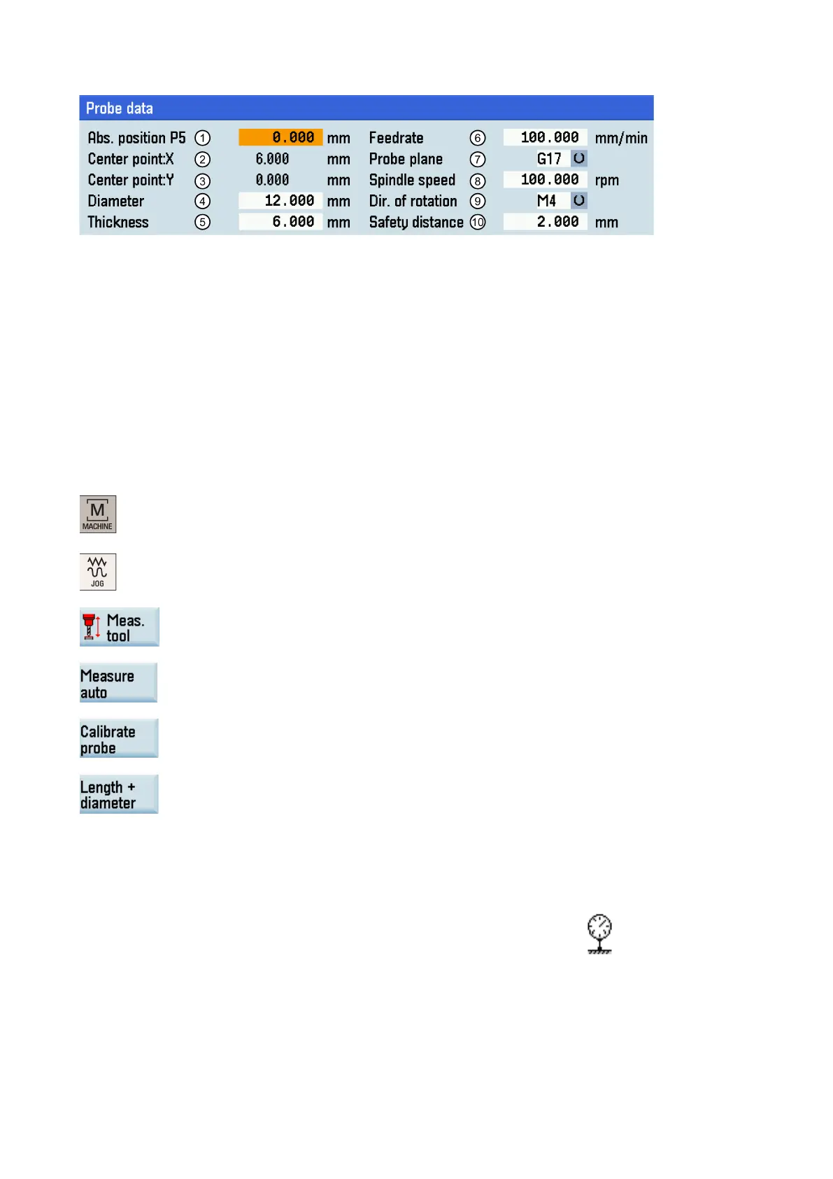
①
Absolute position of the probe in Z direction
/
The measured probe center (the machine coordinate)
eter of the probe (the measured value will be shown after calibrating)
The thickness of the probe
The measurement feedrate in "JOG" mode (this parameter is used to create the measuring program)
G17, G18 and G19 for selection
p.m.
Direction of rotation of the spindle: M3, M4, or M5
⑩
Safety distance between the measuring surface of the probe and the tool
1.
Select the machining operating area.
2.
3.
-level menu for tool measurement.
4.
Open the auto tool measurement window.
5.
Press this vertical softkey to enter the probe calibration screen.
6.
You can use this vertical softkey to choose whether to calibrate the tool length and diam
e-
ter, or to calibrate the tool length only.
7.
Move the tool until it presses down on the
measuring surface of the probe. Then the calibr
a-
tion process is triggered automatically.
When calibrating the probe, make sure the tool is approximately aligned with the center of
the measuring surface of the probe.
During the automatic measureme
nt, a dial gauge symbol ( ) displays, which indicates
hat the measuring process is active.
 Loading...


