3 Safety-Related Functions 11.03
3.5 Safely-reduced speed (SG)
© Siemens AG 2003 All Rights Reserved
3-106 SINUMERIK 840D/SIMODRIVE 611 digital SINUMERIK Safety Integrated (FBSI) - Edition 11.03
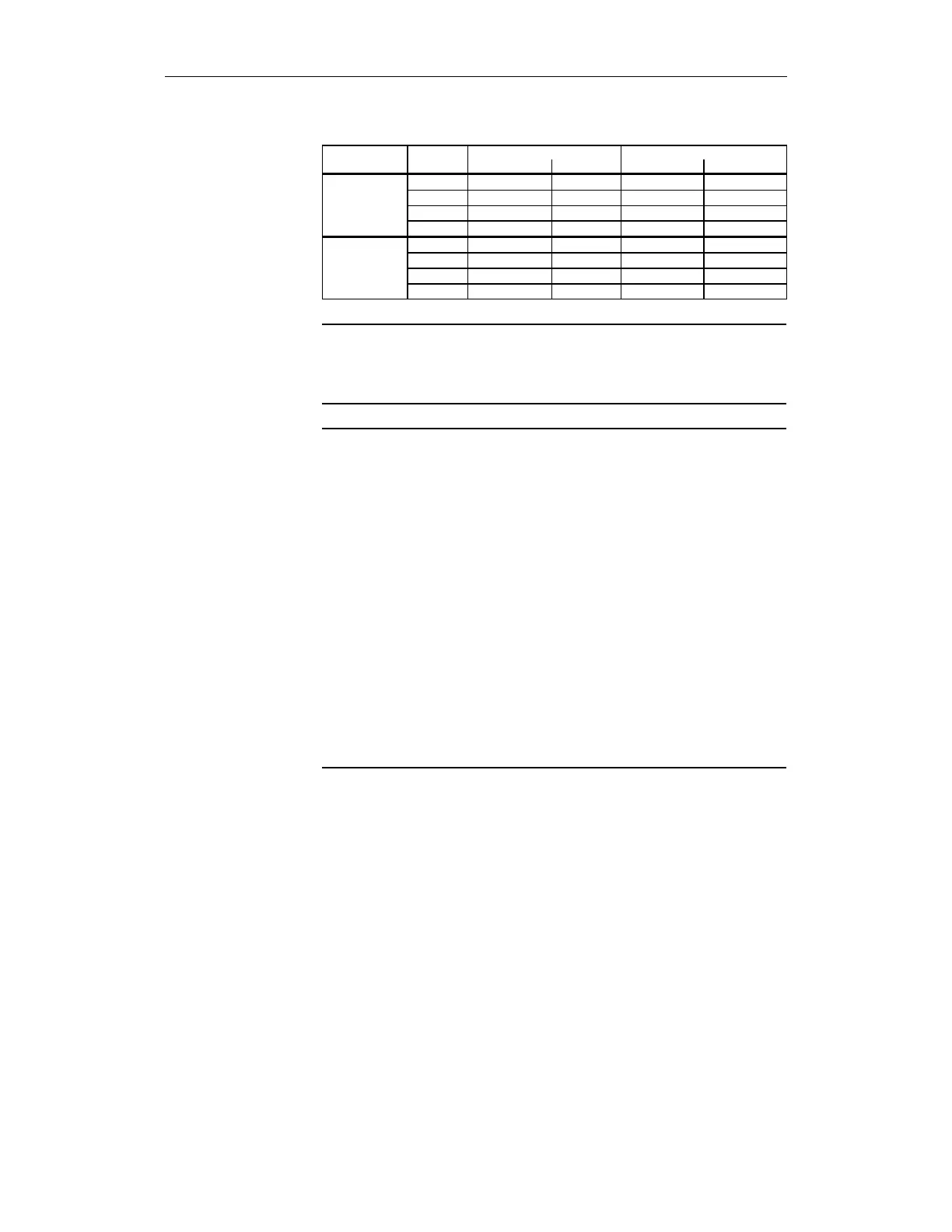
Table3-34 Entering gear ratios into machine data
Stage 840D 611 digital
MD No. Value MD No. Value
Denominator 1
36921[0]
1 1321.0 250
of 2
36921[1]
1 1321.1 400
gearbox 3
36921[2]
1 1321.2 625
encoder/load 4
36921[3]
1 1321.3 1000
Numerator 1
36922[0]
1 1322.0 1000
of 2
36922[1]
1 1322.1 1000
gearbox 3
36922[2]
1 1322.2 1000
encoder/load 4
36922
[
3
]
1 1322.3 1000
Note
For SE/SN, the gear stage must also be changed-over on the NCK side. In
this case, the gear must be changed-over at zero speed or the actual value
synchronization function used.
Note
In the circuit above (Fig. 3-13), the request signals E1/E2 for gear change for
the PLC and drive are supplied from the gear signal.
For SE/SN, the gear stage must also be changed-over on the NCK side.
Because only the pulses of the motor measuring system - and not those of
the direct measuring system - are counted during motion of a motor while
decoupled, this may result in an offset of the SI actual values. As this cannot
be avoided, gear stage changeover without errors is only possible under the
following conditions:
1. The gear stage is selected at zero speed, the time delay does not cause
an offset of the two SI values.
The gear stage is selected when the motor is moving (e.g. oscillating), i.e. the
motor is moving although this cannot be detected at the direct measuring
system. In this case, the following measures can be performed to avoid
errors.
a) MD 36942/or MD 1342 SAFE_POS_TOL must be parameterized as
necessary and re-synchronization of the spindle (<axis DB>.DBX 16.6 or DBX
16.7: active measuring system) must be triggered after gear changeover (if
this has not already been done) to re-align the SI actual values
b) The actual value synchronization function must be used
Example 2: Spindle with a 1-encoder system
• The gear stage is selected from an NC program with an H function via the
PLC user program.
•
Gear ratios are selected through 2 channels.
• The encoder system is connected to the "direct measuring system" input
on the 611 digital closed-loop control module.
• The machine data for the "input assignment gear ratio selection (bits 0,
1, 2)" for the NCK are described in
Chapter 4, "Machine data for SINUMERIK 840D".
Assumptions for
example 2
 Loading...


