11.03 4 Data Descriptions
4.1 Machine data
© Siemens AG 2003 All Rights Reserved
SINUMERIK 840D/SIMODRIVE 611 digital SINUMERIK Safety Integrated (FBSI) - Edition 11.03
4-237
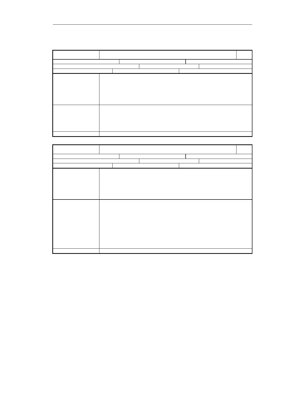
36988
MD number
$MA_SAFE_CAM_PLUS_OUTPUT[n]
Output assignment, SN1 + to SN4 +
840D
Default: 0 Min. input value: 0 Max. input value: -
Change becomes effective after POWER ON: Protection level (R/W) 7/2 Unit: -
Data type: DWORD Applies from SW 3.4
Meaning This data specifies the outputs for plus cams SN1+ to SN4+.
Structure: Refer to coding of output assignment
n = 0, 1, 2, 3 stands for the assignment of plus cams SN1+, SN2+, SN3+, SN4+
Signal means
= 0 Axis is located to the left of the cam (actual value ≤ cam position)
= 1 Axis is located to the right of the cam (actual value > cam position)
(also refer to Chapter 3.7 Safe software cams, output assignment)
Special cases, errors
•
If a single output signal is connected to a terminal, the following applies:
If MD bit 31 is set, then the signal is processed inverted (ss = 81)
• If several output signals are connected to the same terminal, the following applies:
If MD bit 31 is set (ss = 81), the relevant signal is initially inverted.
The (in some cases inverted) output signals are then ANDed and the result output at
the terminal.
Further references MD 36980: $MA_SAFE_SVSS_STATUS_OUTPUT
36989
MD number
$MA_SAFE_CAM_MINUS_OUTPUT[n]
Output assignment, SN1 - to SN4 -
840D
Default: 0 Min. input value: 0 Max. input value: -
Change becomes effective after POWER ON: Protection level (R/W) 7/2 Unit:
Data type: DWORD Applies from SW 3.4
Meaning This data defines the outputs for minus cams SN1- to SN4-.
Structure: Refer to coding of output assignment
n = 0, 1, 2, 3 stands for the assignment of minus cams SN1-, SN2-, SN3-, SN4-
Signal means
= 0 Axis is located to the left of the cam (actual value ≤ cam position)
= 1 Axis is located to the right of the cam (actual value > cam position)
(also refer to Chapter 3.7 Safe software cams, output assignment)
Special cases, errors
• If a single output signal is connected to a terminal, the following applies:
If MD bit 31 is set, then the signal is processed inverted (ss = 81)
Further references MD 36980: $MA_SAFE_SVSS_STATUS_OUTPUT
 Loading...


