4 Data Descriptions 11.03
4.1 Machine data
© Siemens AG 2003 All Rights Reserved
4-238 SINUMERIK 840D/SIMODRIVE 611 digital SINUMERIK Safety Integrated (FBSI) - Edition 11.03
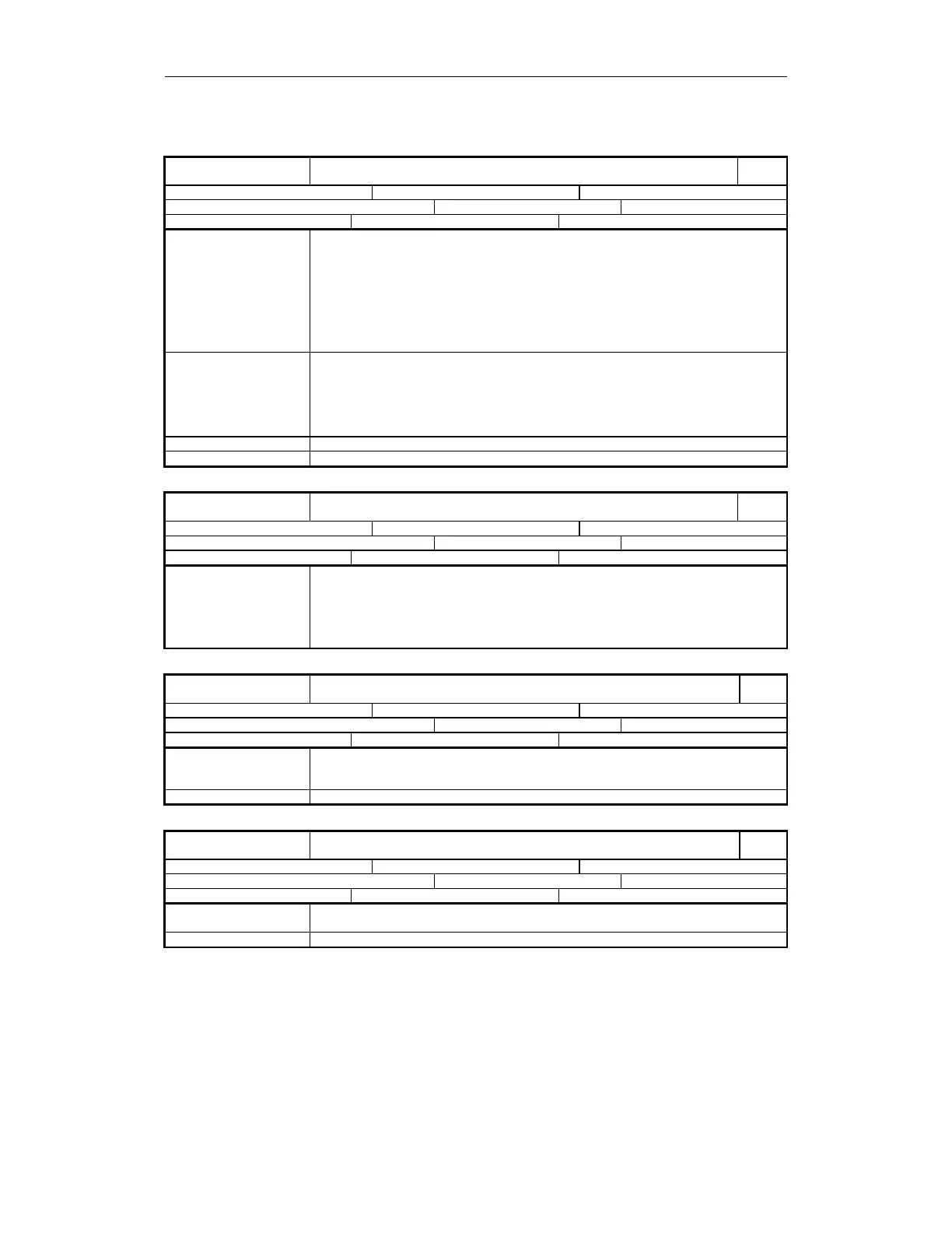
36990
MD number
$MA_SAFE_ ACT_STOP_OUTPUT[n]: 0...3
Output assignment active STOP
840D
Default: 0 Min. input value: 0 Max. input value: -
Change becomes effective after POWER ON: Protection level (R/W) 7/2 Unit: -
Data type: DWORD Applies from SW 4.4.18
Meaning This data defines the assignment of the states
"STOP A/B is active", "STOP C is active" and "STOP D is active" to an output terminal or
system variable.
Structure: Refer to coding of output assignment
n associated status (on "1" level)
n = 0 "STOP A/B is active "
n = 1 "STOP C is active "
n = 2 "STOP D is active "
n = 3 "STOP E is active"
Special cases, errors
•
Test stop can be detected using SGA "Pulse enable".
• "STOP A/B is active" can only be used for "leading brake control" because after the
time specified in MD36956: $MA_SAFE_PULSE_DISABLE_DELAY changeover is
made from STOP B to STOP A.
• "STOP A/B is active", "STOP C is active" and "STOP D is active" can be used for the
forced checking procedure of external STOPs.
Corresponds with … MD 36980: $MA_SAFE_ SVSS_STATUS_OUTPUT
Further references Refer to Chapter 3, "External STOPs"
36992
MD number
$MA_SAFE_CROSSCHECK_CYCLE
Displays axial crosswise comparison clock cycle
840D
Default: 0 Min. input value: 0 Max. input value: -
Change becomes effective after POWER ON: Protection level (R/W) 7/2 Unit: -
Data type: DWORD Applies from SW 6.3
Meaning Indicates effective axial comparison clock cycle in seconds.
Obtained from INFO_SAFETY_CYCLE_TIME and the number of data to be compared
crosswise.
The axial value displayed depends on the associated drive module, since the length of the
crosswise data comparison lists between Performance-1/Standard-2 and Performance-2
modules is different.
36993
MD number
$MA_SAFE_CONFIG_CHANGE_DATE[n]; n=0...4
Date/time of last configuration change of safety-relevant NCK machine data
840D
Default: "Blank" Min. input value: - Max. input value: -
Change becomes effective after POWER ON: Protection level (R/W) 7/2 Unit: -
Data type: STRING Applies from SW 5.2
Meaning Display data which logs when safety-relevant NCK machine data are activated. The last
change is logged in the MD with
field index 0. Previous times in fields 1...4.
Special cases, errors
36994
MD number
$MA_SAFE_PREV_CONFIG[n]; n=0...4
Save data to verify safety configuration changes
840D
Default: "Blank" Min. input value: - Max. input value: -
Change becomes effective after POWER ON: Protection level (R/W) 7/7 Unit: -
Data type: STRING Applies from SW 3.4
Meaning If the safety configuration is changed, safety-relevant configuration data is stored in this
field.
Special cases, errors
 Loading...


