4 Data Descriptions 11.03
4.2 Machine data for SIMODRIVE 611 digital
© Siemens AG 2003 All Rights Reserved
4-252 SINUMERIK 840D/SIMODRIVE 611 digital SINUMERIK Safety Integrated (FBSI) - Edition 11.03
1391
1392
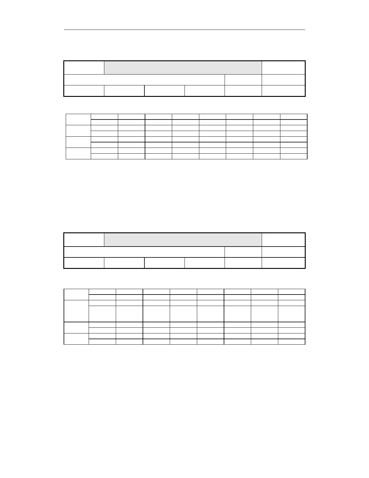
$MD_SAFE_DIAG_NC_RESULTLIST1
$MD_SAFE_DIAG_611digital_RESULTLIST1
611 digital
Diagnostics, NC result list 1
Diagnostics, 611 digital result list 1
Relevant for:
FD/MSD
Unit:
-
Default:
0
Minimum value:
0
Maximum value:
FFFF FFFF
Data type:
Long integer
Becomes effective:
POWER ON
This machine data is used to decode errors in result list 1.
Bit No. Bit 31 Bit 30 Bit 29 Bit 28 Bit 27 Bit 26 Bit 25 Bit 24
Function - - - - - - - -
Bit No. Bit 23 Bit 22 Bit 21 Bit 20 Bit 19 Bit 18 Bit 17 Bit 16
Function - - - - - - - -
Bit No. Bit 15 Bit 14 Bit 13 Bit 12 Bit 11 Bit 10 Bit 9 Bit 8
Function - - SG4 SG4 SG3 SG3 SG2 SG2
Bit No. Bit 7 Bit 6 Bit 5 Bit 4 Bit 3 Bit 2 Bit 1 Bit 0
Function SG1 SG1 SE2 SE2 SE1 SE1 SBH SBH
The bits assigned to SI functions have an identical status when there is no
error, but have different states when there is an error.
In the case of a difference between 1391 and 1392, an error has occurred in
the SI function that is assigned to this bit.
Example:
MD 1391 = 0000 1556
Hex
= 0000 0000 0000 0000 0001 0101 0101 0110
Binary
MD 1392 = 0000 1557
Hex
= 0000 0000 0000 0000 0001 0101 0101 0111
Binary
--> Bit 0 is different --> error in the result cross-check of the safe operating stop
(SBH function). Data that is relevant for the safe operating stop function must
be checked in the NCK and drive channels.
1393
1394
$MD_SAFE_DIAG_NC_RESULTLIST2
$MD_SAFE_DIAG_611digital_RESULTLIST2
611 digital
Diagnostics, NC result list 2
Diagnostics, 611 digital result list 2
Relevant for:
FD/MSD
Unit:
-
Default:
0
Minimum value:
0
Maximum value:
FFFF FFFF
Data type:
Long integer
Becomes effective:
POWER ON
This machine data is used to decode errors in result list 2.
Bit No. Bit 31 Bit 30 Bit 29 Bit 28 Bit 27 Bit 26 Bit 25 Bit 24
Function - - - - - - - -
Bit No. Bit 23 Bit 22 Bit 21 Bit 20 Bit 19 Bit 18 Bit 17 Bit 16
Function - - Cam
modulo
range
Cam
modulo
range
n
x
lower
limit
n
x
lower
limit
n
x
upper
limit
n
x
upper
limit
Bit No. Bit 15 Bit 14 Bit 13 Bit 12 Bit 11 Bit 10 Bit 9 Bit 8
Function SN4 - SN4 - SN4 + SN4 + SN3 - SN3 - SN3 + SN3 +
Bit No. Bit7 Bit6 Bit5 Bit4 Bit 3 Bit 2 Bit 1 Bit 0
Function SN2 - SN2 - SN2 + SN2 + SN1 - SN1 - SN1 + SN1 +
The bits assigned to SI functions have an identical status when there is no
error, but have different states when there is an error.
In the case of a difference between 1393 and 1394, an error has occurred in
the SI function that is assigned to this bit.
Example:
MD 1393 = 0000 1547
Hex
= 0000 0000 0000 0000 0001 0101 0100 0111
Binary
MD 1394 = 0000 1557
Hex
= 0000 0000 0000 0000 0001 0101 0101 0111
Binary
--> Bit 4 is different --> error in result cross-check of safe cam (SN2 +). Data
that is relevant for this cam must be checked in the NCK and drive channels.