7 Configuring example 11.03
7.3 Safety Integrated with SPL
© Siemens AG 2003 All Rights Reserved
7-382 SINUMERIK 840D/SIMODRIVE 611 digital SINUMERIK Safety Integrated (FBSI) - Edition 11.03
113
111
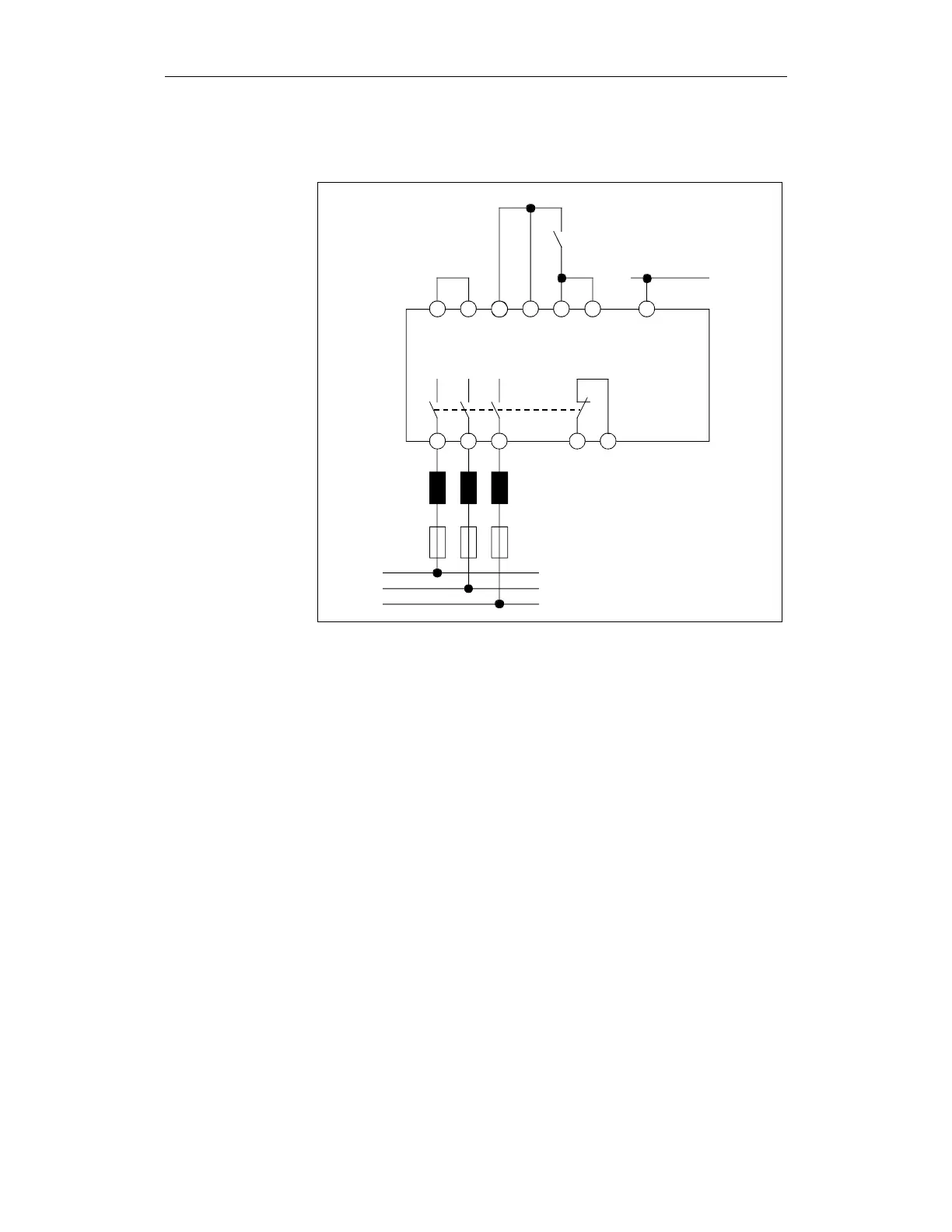
NS1 NS2 9 64 63 48 19
of power switch
0V
ER_MODUL.DSF
Leading contact
Fig. 7-6 I/R module
The two main contacts of the Emergency Stop button are supplied with 24 V
(three-terminal concept) via the PLC output. This PLC output is used for the
forced checking procedure of the inputs and outputs (refer to Chapter 7.3.6
"Test stop"). The individual circuits of the Emergency Stop button are
separately connected to the PLC and NCK inputs.
Circuit diagram
Description