11.03 7 Configuring example
7.3 Safety Integrated with SPL
© Siemens AG 2003 All Rights Reserved
SINUMERIK 840D/SIMODRIVE 611 digital SINUMERIK Safety Integrated (FBSI) - Edition 11.03
7-383
PLC
PLC
NCK
I1
Q48.1
I76.0
11
21
12
22
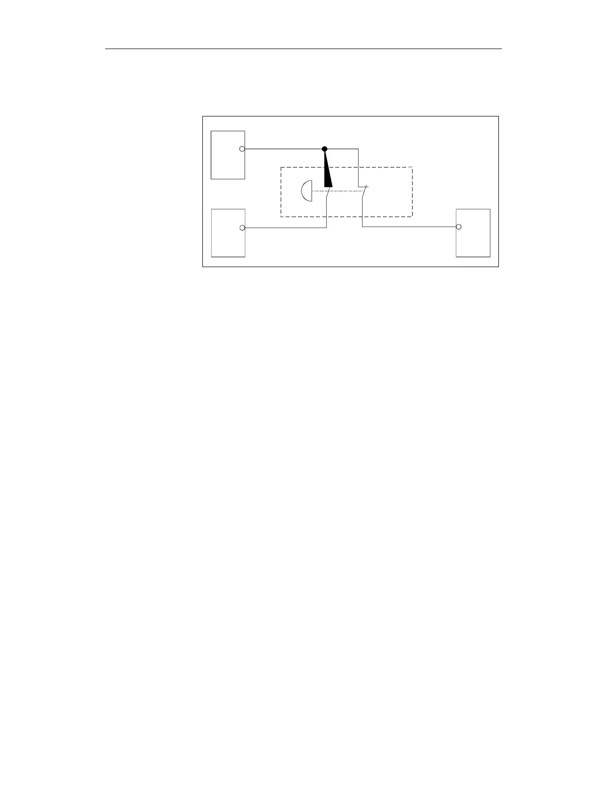
EMERGENCY STOP
button
NOTAUS1.DSF
Fig. 7-7 EMERGENCY STOP button
The power to the external actuators is disconnected in the cabinet using two
contactors that are controlled redundantly by the PLC and the NC. The power
contacts are connected in series and therefore disconnect the power through
two channels when an EMERGENCY STOP is initiated.
One signaling contact of each of the two contactors is connected in series to
the input of the PLC. This PLC input is also used for the forced checking
procedure of the inputs and outputs (refer to Chapter 7.3.6 "Test stop").
Circuit diagram
Description
 Loading...


