EasyManua.ls Logo

Siemens SINUMERIK Series User Manual

Siemens SINUMERIK Series
940 pages
To Next Page IconTo Next Page
To Previous Page IconTo Previous Page
Page #202 background imageLoading...
Page #202 background image
6.7.2 Continuing program from search target
To continue the program at the desired position, press the <CYCLE START> key twice.
The first CYCLE START outputs the auxiliary functions collected during the search. The
program is then in the Stop state.
Before the second CYCLE START, you can use the "Overstore" function to create states
that are required, but not yet available, for the further program execution.
By changing to the JOG REPOS mode, you can also manually traverse the tool from the
current position to the setpoint position, if the setpoint position is not to be automatically
approached after the program start
6.7.3 Simple search target definition
Requirement
The program is selected and the controller is in Reset mode.
Procedure
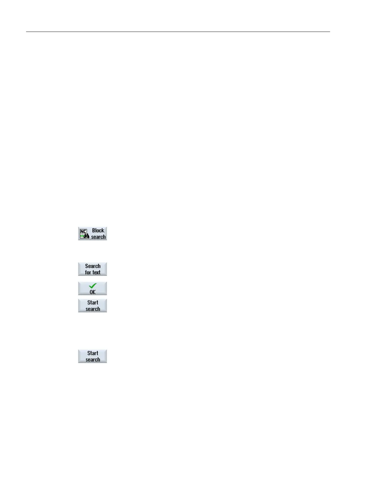
1. Press the "Block search" softkey.
2. Place the cursor on a particular program block.
- OR -
Press the "Find text" softkey, select the search direction, enter the
search text and confirm with "OK".
3. Press the "Start search" softkey.
The search starts. Your specified search mode will be taken into ac‐
count.
The current block will be displayed in the "Program" window as soon
as the target is found.
4. If the located target (for example, when searching via text) does not
correspond to the program block, press the "Start search" softkey again
until you find your target.
Press the <CYCLE START> key twice.
Processing is continued from the defined position.
Machining the workpiece
6.7 Starting machining at a specific point
Milling
202 Operating Manual, 08/2018, 6FC5398-7CP41-0BA0

Table of Contents

Other manuals for Siemens SINUMERIK Series

Question and Answer IconNeed help?

Do you have a question about the Siemens SINUMERIK Series and is the answer not in the manual?

Siemens SINUMERIK Series Specifications

General IconGeneral
Axes ControlUp to 31 axes
CategoryControl Unit
ManufacturerSiemens
SeriesSINUMERIK
Control TypeCNC
Communication InterfacesEthernet, USB
Operating Temperature0°C to 45°C
Protection ClassIP20
Power Supply24V DC
DisplayColor TFT LCD

Summary

Fundamental safety instructions

General safety instructions

Provides essential safety guidelines and information on residual risks for safe operation.

Warranty and liability for application examples

Clarifies the non-binding nature of application examples and user responsibility for correct operation.

Industrial security

Details Siemens' industrial security functions and customer responsibilities for network protection.

Introduction

Product overview

Introduces the SINUMERIK control system as a CNC for machine tools and its basic functions.

Operator panel fronts

Describes the display and operation components of the SINUMERIK Operate user interface.

Machine control panels

Illustrates operator controls and displays of a Siemens machine control panel.

User interface

Details the screen layout, status display, actual values, T,F,S window, and program control.

Multitouch operation with SINUMERIK Operate

Multitouch panels

Discusses optimization for multitouch operation and compatible operator panels.

Touch-sensitive user interface

Provides guidance on using thin gloves for touch-sensitive glass interfaces with capacitive touch function.

Finger gestures

Explains various finger gestures like tap, tap with 2 fingers, and flick gestures for operation.

Multitouch user interface

Details screen layout, function key block, further operator controls, virtual keyboard, and special characters.

Setting up the machine

Switching on and switching off

Describes the procedure for powering the control system on and off.

Approaching a reference point

Explains the process of referencing axes and user agreement for safety integrated functions.

Operating modes

Details the different operating modes like JOG, REF POINT, REPOS, MDI, AUTO, and TEACH IN.

Settings for the machine

Covers switching coordinate systems, units of measurement, and setting zero offsets.

Measure tool

Provides procedures for manually and automatically measuring drilling, milling, and turning tools.

Measuring the workpiece zero

Details methods for manual and automatic measurement of workpiece zero points.

Zero offsets

Explains base offset, coarse and fine offsets, and how to display and edit them.

Monitoring axis and spindle data

Describes how to specify working area limitations and edit spindle data.

Displaying setting data lists

Explains how to display lists with configured setting data.

Handwheel assignment

Details how to assign axes to the handwheel for traversing.

MDA

Covers Manual Data Input mode, including loading, saving, and editing G-code programs.

Execution in manual mode

General

Introduces manual mode operations, including reference point approach and manual control.

Selecting a tool and spindle

Explains how to select tools and control the spindle in manual mode using T, S, M windows.

Traversing axes

Details how to traverse axes using Increment or Axis keys, or handwheels.

Positioning axes

Explains how to traverse individual or several axes to specific positions for machining sequences.

Swiveling

Describes manual swivel functions for setup, measurement, and machining with swiveled surfaces.

Manual retraction

Explains the Retract function for drilling tools in JOG mode, useful when the coordinate system is swiveled.

Machining the workpiece

Starting and stopping machining

Details how to start and stop machining operations, including program execution and interruption.

Selecting a program

Guides on selecting programs from the Program Manager for execution.

Testing a program

Explains how to test programs using single block or other program control methods.

Displaying the current program block

Describes how to view the current program block, machining times, and G code highlighting.

Correcting a program

Details options for correcting part programs, including stop state and reset status.

Repositioning axes

Explains how to move the tool away from the contour after an interruption and resume program execution.

Starting machining at a specific point

Covers methods for starting machining at specific points using block search and search pointer.

Block search mode

Details different block search modes, including 'with calculation' and 'without calculation'.

Block search to a position pattern for ShopMill programs

Explains how to perform block search based on position patterns in ShopMill programs.

Controlling the program run

Describes program control options like PRT, DRY, RG0, M01, M101, DRF, SKP, GCC, and MRD.

Skip blocks

Explains how to skip program blocks that are not to be executed every time the program runs.

Overstore

Covers the option to execute technological parameters before the program starts.

Editing a program

Details how to use the editor to render, supplement, or change part programs.

Working with DXF files

Explains how to open, clean, enlarge, reduce, and change sections of DXF files.

Simulating machining

Overview

Introduces simulation, graphic display, blank definition, and traversing paths.

Simulation before machining of the workpiece

Describes performing a quick run-through to graphically display program execution.

Simultaneous recording before machining of the workpiece

Explains graphically displaying program execution for monitoring results before actual machining.

Simultaneous recording during machining of the workpiece

Details how to track program execution on screen while machining is active.

Different views of the workpiece

Covers various display views like Top, 3D, Side, Turn, Half cut, and Machine space.

Editing the simulation display

Explains how to edit the simulation display, including blank display and tool path control.

Program control during the simulation

Details how to change feedrate and simulate program block by block.

Changing and adapting a simulation graphic

Explains how to enlarge, reduce, pan, rotate graphics, and define cutting planes.

Displaying simulation alarms

Describes how to display and acknowledge simulation alarms.

Generating a G code program

Graphical programming

Covers technology-oriented step selection, input windows, online help, and contour input.

Program views

Explains how to display G code programs in various views like program view and parameter screen.

Program structure

Details the structure of G code programs including header, blocks, and end of program.

Fundamentals

Covers essential concepts like machining planes and current planes in cycles.

Programming a tool (T)

Explains how to call and program tools (T) and other parameters like M, S, F.

Generating a G code program

Guides on creating new part programs and specifying desired G code commands.

Blank input

Details how to define the shape and dimensions of the workpiece blank for simulation.

Machining plane, milling direction, retraction plane, safe clearance and feedrate (PL, RP, SC, F)

Explains general parameters for cycles including machining plane, milling direction, and safety clearance.

Selection of the cycles via softkey

Provides an overview of available machining steps and how to insert them via softkeys.

Calling technology functions

Covers hiding cycle parameters, setting data for cycles, and checking cycle parameters.

Creating a ShopMill program

Program views

Explains how to display ShopMill programs in Work plan, Graphic view, or Parameter screen.

Program structure

Details the division of a machining step program into sub-areas: header, blocks, and end.

Fundamentals

Covers machining planes and polar coordinates for workpiece dimensioning.

Creating a ShopMill program

Guides on creating new ShopMill programs, including header and end blocks.

Program header

Details parameters affecting the entire program, like blank dimensions and retraction planes.

Generating program blocks

Explains how to define individual machining steps in program blocks.

Tool, offset value, feed and spindle speed (T, D, F, S, V)

Covers essential parameters for program blocks: tool, offset, feedrate, and spindle speed/direction.

Defining machine functions

Describes how to switch coolant on/off and define machine functions or custom texts.

Call work offsets

Explains how to call work offsets (G54, etc.) from any program and define them in lists.

Repeating program blocks

Details how to repeat program blocks using start and end markers for efficiency.

Specifying the number of workpieces

Explains how to control program repetition for producing multiple workpieces.

Changing program blocks

Guides on optimizing parameters in programmed blocks or adapting them to new situations.

Changing program settings

Describes how to change parameters defined in the program header at any location.

Selection of the cycles via softkey

Provides an overview of available machining steps and how to select them via softkeys.

Programming technological functions (cycles)

Drilling

Covers general parameters, centering, drilling, reaming, deep-hole drilling, and tapping cycles.

Milling

Details face milling, rectangular pocket, circular pocket, spigot, groove, thread milling, and engraving cycles.

Contour milling

Explains how to mill simple or complex contours, defining elements, and creating new contours.

Turning - milling/turning machine

Covers stock removal, groove, undercut, thread turning, and cut-off cycles.

Contour turning - Milling/turning machine

Details contour turning, stock removal, grooving, and undercut functions.

Further cycles and functions

Covers swivel plane/tool, aligning turning tools, high-speed settings, subroutines, and transformations.

Additional cycles and functions in ShopMill

Explains transformations, translation, rotation, scaling, mirroring, cylinder surface transformation, and straight/circular machining.

Multi-channel view

Multi-channel view

Introduces the multi-channel view for simultaneously viewing several channels.

Multi-channel view in the "Machine" operating area

Details displaying and switching channels in the Machine operating area.

Multi-channel view for large operator panels

Explains displaying up to four channels on OP015/OP019 panels or PC.

Setting the multi-channel view

Guides on configuring view settings for multi-channel or single-channel operation.

Collision avoidance

Activate collision avoidance

Describes the procedure to activate collision avoidance in AUTO, JOG, or MDA modes.

Set collision avoidance

Explains how to activate or deactivate collision monitoring separately for machine and tools.

Tool management

Lists for the tool management

Details available lists: Tool list, Tool wear, Magazine, and Tool data OEM.

Magazine management

Explains functions for managing magazines and tool locations.

Tool types

Describes various tool types available for creating new tools.

Tool dimensioning

Provides an overview of the dimensioning for different tool types.

Tool list

Details tool parameters like location, type, name, and geometry data.

Tool wear

Explains monitoring tools' working times, wear, and reactivation.

Tool data OEM

Describes options for configuring OEM tool data.

Magazine

Details tool parameters related to magazines and locations.

Tool details

Explains how to display tool data, cutting edge data, and monitoring data.

Changing a tool type

Guides on changing the tool type in the tool list favorites or special tool types.

Graphic display

Describes displaying tools and magazine locations in a dynamic graphic display.

Sorting tool management lists

Explains how to sort tool lists by criteria like magazine location, name, or tool type.

Filtering the tool management lists

Details the filter function to display tools with specific properties.

Specific search in the tool management lists

Explains how to search for tools, magazine locations, or empty locations.

Settings for tool lists

Covers options for setting the view in tool lists, like displaying only one magazine.

Working with Multitool

Explains storing more than one tool at a magazine location and managing multitool data.

Managing programs

Overview

Covers accessing programs for execution, editing, copying, or renaming via Program Manager.

Opening and closing the program

Guides on opening programs in the editor for viewing or modification and closing them.

Executing a program

Explains how to select and execute programs from NC memory, local drives, or external media.

Creating a directory / program / job list / program list

Details file and directory naming rules, creating new directories, workpieces, G code, and ShopMill programs.

Creating templates

Describes storing own templates for creating part programs and workpieces.

Searching directories and files

Explains how to search for directories and files in the Program Manager using place holders.

Displaying the program in the Preview

Shows how to view program content in a preview before starting editing.

Selecting several directories/programs

Explains how to select multiple files and directories for further processing.

Copying and pasting a directory/program

Guides on copying and pasting directories or programs for creating new ones or exchanging data.

Deleting a program/directory

Explains how to delete programs or directories to maintain a clearer data overview.

Changing file and directory properties

Details how to display and change file and directory properties, including access rights.

Set up drives

Covers configuring logical drives like USB, network drives, and CompactFlash cards.

Viewing PDF documents

Explains how to display PDF and HTML documents via the Program Manager.

EXTCALL

Describes using the EXTCALL command to access files on local drives, USB, or network drives.

Execution from external memory (EES)

Explains direct execution of part programs from configured drives without restrictions.

Backing up data

Covers generating archives in Program Manager and via system data.

Setup data

Explains backing up tool data, zero point settings, and job lists.

Backing up parameters

Covers backing up R-parameters and global user variables for specific programs.

RS-232-C

Details reading in and reading out archives via serial interface and setting V24 parameters.

Multiple clamping

Explains optimizing tool changes over multiple workpiece clampings using ShopMill programs.

Alarm, error, and system messages

Displaying alarms

Covers displaying all upcoming alarms and acknowledging them with relevant information.

Displaying an alarm log

Details how to display and save the machine history of alarms and messages.

Displaying messages

Explains how to display PLC and part program messages issued during machining.

Sorting, alarms, faults and messages

Describes sorting alarms, messages, and logs by date or number.

Creating screenshots

Guides on creating and saving screenshots of the current user interface.

PLC and NC variables

Details displaying and editing PLC and NC variables, including formats and notation examples.

Version

Explains how to display version data for system software, PLC programs, and hardware components.

Logbook

Covers editing logbook entries, making new entries, and searching for specific entries.

Remote diagnostics

Details setting remote access, permitting modem access, and requesting remote diagnostics.

Working with Manual Machine

Manual Machine

Introduces Manual Machine mode for carrying out machining processes without programming.

Measuring the tool

Explains how to measure tool offset data using manual and automatic measurement.

Measuring the workpiece zero

Details methods for determining workpiece zero using various elements.

Setting the zero offset

Guides on directly selecting work offsets in the Parameter area.

Set limit stop

Explains how to limit the traversing range of axes by entering values for limit stops.

Simple workpiece machining

Describes machining workpieces directly in JOG mode for axis movements, angular milling, and straight/circular machining.

More complex machining

Covers functions for more extensive machining like drilling, milling, contour milling, and turning.

Simulation and simultaneous recording

Explains how to check machining results using simulation without traversing axes.

Teaching in a program

Overview

Introduces the Teach-in function for editing programs and creating simple traversing blocks.

General sequence

Describes the general sequence for selecting program blocks and traversing axes.

Inserting a block

Guides on traversing axes and writing actual values directly to a new position block.

Teach-in via window

Explains how to teach-in positions for G0, G1, and circle end points using windows.

Editing a block

Details how to overwrite a program block with a teach-in block of the same type.

Selecting a block

Explains setting the interrupt pointer and changing program areas.

Deleting a block

Describes the option to delete a program block entirely.

Settings for teach-in

Covers defining axes for teach-in blocks and motion/transition parameters.

HT 8 (840D sl only)

HT 8 overview

Combines operator panel and machine control panel functions for monitoring, operating, teaching, and programming.

Traversing keys

Explains the unlabeled traversing keys and how to display labels on the vertical softkey bar.

Machine control panel menu

Details selecting keys from the machine control panel via touch operation of softkeys.

Virtual keyboard

Describes using the virtual keyboard as an input device for touch operator panels.

Calibrating the touch panel

Explains the necessity and procedure for calibrating the touch panel upon first connection.

Ctrl-Energy

Functions

Introduces options to improve machine energy utilization via Ctrl-Energy.

Ctrl-E analysis

Provides an overview of energy consumption, displaying current power, energy usage, and comparison measurements.

Ctrl-E profiles

Details defining and activating energy-saving profiles for optimizing consumption.

Easy Message (828D only)

Overview

Enables machine state notifications via SMS messages using a connected modem.

Activating Easy Message

Covers commissioning the modem connection and activating the SIM card.

Creating/editing a user profile

Guides on setting up user identification, telephone numbers, and selecting events for SMS notification.

Setting-up events

Details configuring events for SMS notification, including programmed messages and alarms.

Logging an active user on and off

Explains how to activate users for SMS messages via HMI commands or SMS.

Displaying SMS logs

Describes how to view SMS data traffic and assign activities to fault situations.

Making settings for Easy Message

Covers changing messenger configuration, setting SMS counter, and using default settings.

Easy Extend

Overview

Introduces Easy Extend for retrofitting machines with additional PLC-controlled devices.

Enabling a device

Guides on enabling available device options, which may be protected by a password.

Activating and deactivating a device

Explains how to select, activate, and deactivate devices in the list.

Initial commissioning of additional devices

Covers commissioning additional devices subsequently, for example, when retrofitting.

Edit PLC user program (828D only)

Introduction

Explains PLC user programs, logical operations, and ladder diagram display.

Displaying and editing PLC properties

Covers displaying and editing PLC properties like operating state, project name, and cycle time.

Displaying and editing PLC and NC variables

Details displaying and editing PLC/NC variables, including formats, notation examples, and inserting variables.

View of the program blocks

Explains how to display logic and graphic information of program blocks, including status and symbolic address.

Related product manuals