Procedure
1. The part program or ShopMill program to be processed has been created
and you are in the editor.
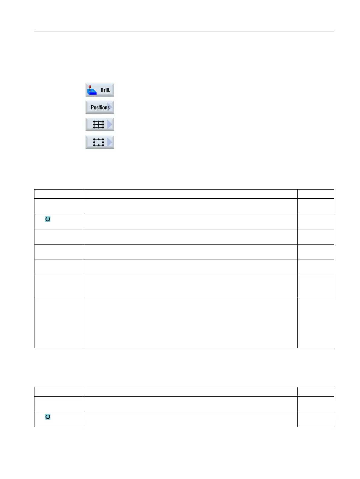
2. Press the "Drilling" softkey.
3. Press the "Positions" softkey.
4. Press the "Grid" softkey.
- OR -
Press the "Frame" softkey.
The "Position grid" or "Position frame" input window opens.
Parameters - "Grid" position pattern
Parameter Description Unit
LAB
(only for G code)
Repeat jump label for position
PL
(only for G code)
Machining plane
Z0 (only for Shop‐
Mill)
Z coordinate of reference point Z (abs) mm
X0 X coordinate of the reference point X (abs)
This position must be programmed absolutely in the 1st call.
mm
Y0 Y coordinate of the reference point Y (abs)
This position must be programmed absolutely in the 1st call.
mm
α0 Angle of rotation of the line referred to the X axis
Positive angle: Line is rotated counter-clockwise.
Negative angle: Line is rotated clockwise.
Degrees
αX
αY
L1
L2
N1
N2
Shear angle X
Shear angle Y
Distance between columns
Distance between rows
Number of columns
Number of rows
Degrees
Degrees
mm
mm
Parameters - "Frame" position pattern
Parameter Description Unit
LAB
(only for G code)
Repeat jump label for position
PL
(only for G code)
Machining plane
Programming technological functions (cycles)
10.1 Drilling
Milling
Operating Manual, 08/2018, 6FC5398-7CP41-0BA0 413