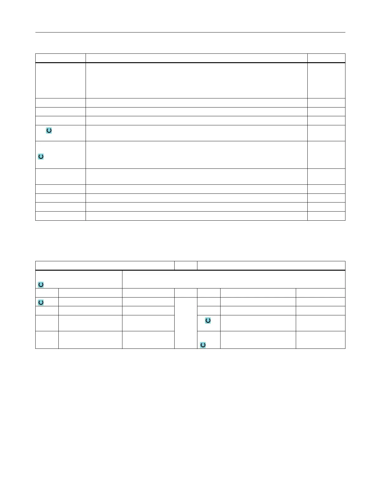
Parameter Description Unit
X0
Y0
Z0
The positions refer to the reference point:
Reference point X – (for single position only)
Reference point Y – (for single position only)
Reference point Z – (single position only and G Code position pattern)
mm
mm
mm
W Slot width mm
L Slot length mm
α0 Angle of rotation of slot Degrees
Z1 Slot depth (abs) or depth relative to Z0 (abs) – (only for ∇, ∇∇∇, ∇∇∇ base and ∇∇∇ rough
finishing)
mm
DXY
● Maximum plane infeed
● Maximum plane infeed as a percentage of the milling cutter diameter
- (only for ∇)
mm
%
DZ Maximum depth infeed - (only for ∇, ∇∇∇ rough finishing, ∇∇∇ and ∇∇∇ edge)
- (only for vortex milling)
mm
UXY Plane finishing allowance (slot edge) - (only for ∇, ∇∇∇ rough finishing and ∇∇∇ base) mm
UZ Depth finishing allowance (slot base) - (only for ∇, ∇∇∇ rough finishing and ∇∇∇ edge ) mm
FS Chamfer width for chamfering (inc) - (for chamfering only) mm
ZFS Insertion depth of tool tip (abs or inc) - (for chamfering only) mm
* Unit of feedrate as programmed before the cycle call
Parameters in the "Input simple" mode
G code program parameters ShopMill program parameters
Input
● simple
Milling direction T Tool name
RP Retraction plane mm D Cutting edge number
F Feedrate * F Feedrate mm/min
mm/rev
S / V Spindle speed or constant
cutting rate
rpm
m/min
Programming technological functions (cycles)
10.2 Milling
Milling
Operating Manual, 08/2018, 6FC5398-7CP41-0BA0 467