EasyManuals Logo

Siemens SIPROTEC 5 Series User Manual

Siemens SIPROTEC 5 Series
254 pages
To Next Page IconTo Next Page
To Previous Page IconTo Previous Page
Page #162 background imageLoading...
Page #162 background image
²
Remove the device completely.
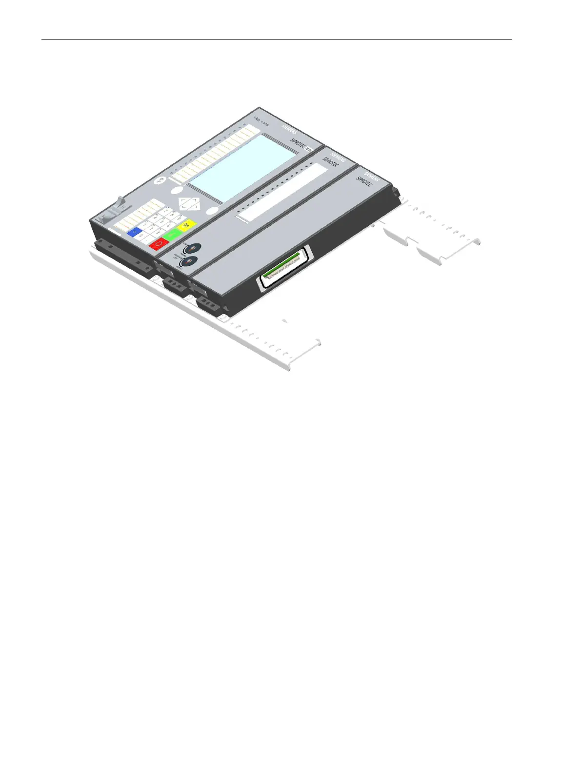
Assembling the On-Site Operation Panel into One Block
[dwaublo1-040211-01.tif, 2, --_--]
Figure 5-6
On-Site Operation Panel Fitted on Mounting Bracket
²
Place the 2 mounting brackets intended for expansion in parallel to one another on a flat surface.
²
Bolt the 1st (left-hand) on-site operation panel to the 2 mounting brackets. Do not firmly tighten the
screws.
²
Place the 2nd on-site operation panel on the right of the 1st one and screw these panels onto the 2
mounting brackets. Do not firmly tighten the screws. Make sure that the snap-in spring is engaged!
²
Bolt the 2 operation panels to one another through the contact tab. Do not firmly tighten the screws.
²
Repeat the last 2 steps for the remaining operation panels. Leave all screws loose.
Assembling the Devices
²
Remove the distance frame from the expansion module.
²
Remove the bus cover from the extreme left-hand module.
²
Remove the plastic screw covers from the extreme left-hand module and from the expansion module.
²
Place the expansion module on the left next to the device. Insert the 2 hinged angle clips of the expan-
sion module in the cut-outs of the device.
²
Swivel the expansion module in the direction of the device so that the bottom snap-in spring engages.
²
Bolt the contact tab to the 2 modules.
Installation and Commissioning
²
Install the distance frame intended for expansion.
²
Wire and, if required, fasten the current and voltage terminal blocks.
Working on the Device
5.2 Expanding Modular Devices
162 SIPROTEC 5, Hardware Description, Manual
C53000-G5040-C002-C, Edition 10.2017

Table of Contents

Questions and Answers:

Question and Answer IconNeed help?

Do you have a question about the Siemens SIPROTEC 5 Series and is the answer not in the manual?

Siemens SIPROTEC 5 Series Specifications

General IconGeneral
Protection FunctionsOvercurrent, differential, distance, over/under voltage, frequency
Communication ProtocolsIEC 61850, IEC 60870-5-103, Modbus, DNP3, PROFINET
DisplayGraphical LCD with touch functionality
Inputs/OutputsDigital and analog inputs/outputs, configurable
Power Supply24-250V DC or 100-240V AC
MountingPanel or rack mounting
Environmental ConditionsOperating temperature: -25°C to +70°C, humidity up to 95% non-condensing
Product TypeMultifunctional protection relay
ApplicationPower generation, transmission, distribution, industrial plants
CybersecurityIEC 62351, role-based access control, secure communication
Modular DesignYes, with plug-in modules for flexibility
HardwareRobust design with high processing power
SoftwareSIPROTEC 5 DIGSI software for configuration and operation
Control FunctionsRemote control, switching sequences, interlocking
Monitoring FunctionsEvent recording, disturbance recording, measurement values
HMIIntegrated HMI with graphical display and pushbuttons. Remote HMI via web browser or dedicated software. User-configurable dashboards and single-line diagrams.
Time SynchronizationIRIG-B, SNTP, PTP (IEEE 1588)
CertificationsIEC, IEEE, UL, CE

Related product manuals