LEDs of the RJ45 Terminals
The light-emitting diodes (LEDs) signal the operating state of the communication connection. The operating
states are explained in the following table:
COM Link (RJ45) Signal Color Operating State
LED 1 CL2_LED0_N Yellow Flashes when a communication module is inserted in
plug-in module position P.
LED 2 CL3_LED0_N Green Flashes when a communication module is inserted in
plug-in module position N.
Terminals
Overview of Terminals
[dwcb202p-030211-01.tif, 2, --_--]
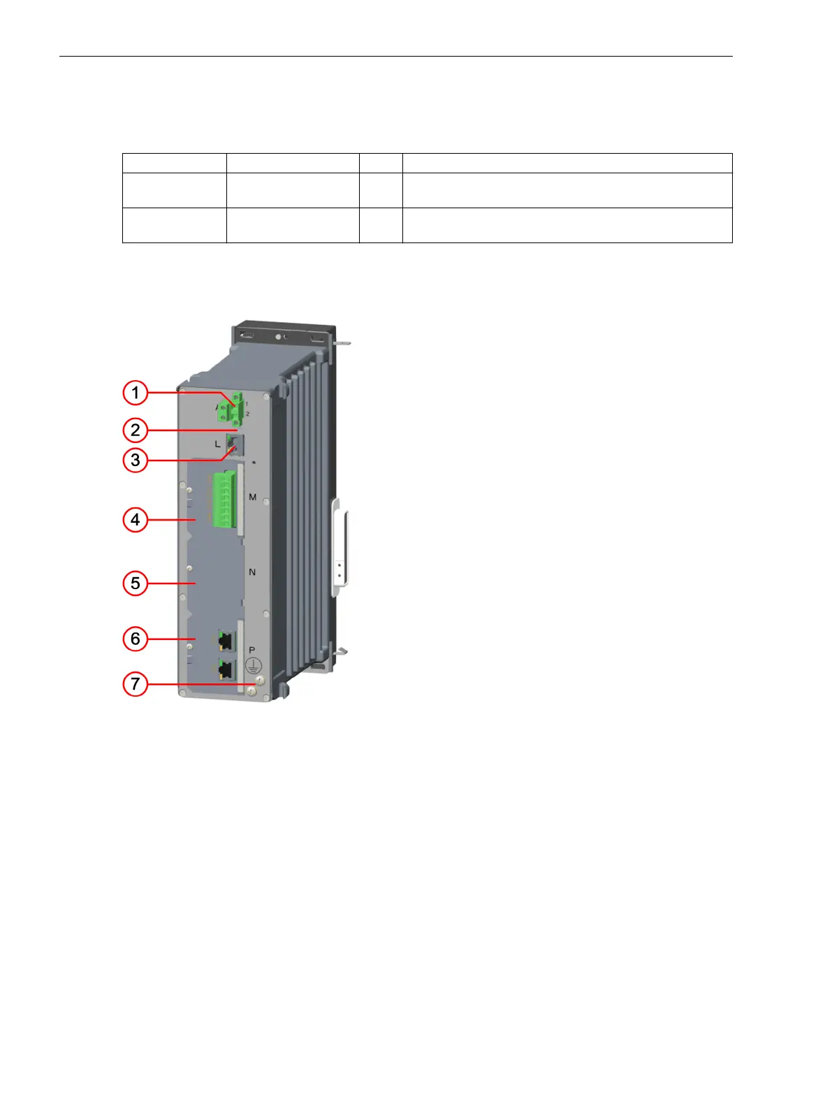
Figure 3-10
CB202 – Terminals
(1) 2-pole terminal to connect power supply
(2) LED: Power On
(3) COM link
(4) Plug-in module position M (for measuring-transducer modules only – equipped in this example
with an ANAI module)
(5) Plug-in module position N (for measuring-transducer or communication modules)
(6) Plug-in module position P (for measuring-transducer or communication modules – equipped in
this example with an ETH-BA-2EL module)
(7) Protective grounding terminal
The Ethernet connection to the base module is established at the COM link terminal.
The 2-pole voltage terminal is used for the external power supply (see Figure 3-12).
3.1.4.2
Electronic Modules
3.1 Power-Supply Modules of the Modular Devices
52 SIPROTEC 5, Hardware Description, Manual
C53000-G5040-C002-C, Edition 10.2017

 Loading...


