[tdio214x-270812-01.tif, 1, en_US]
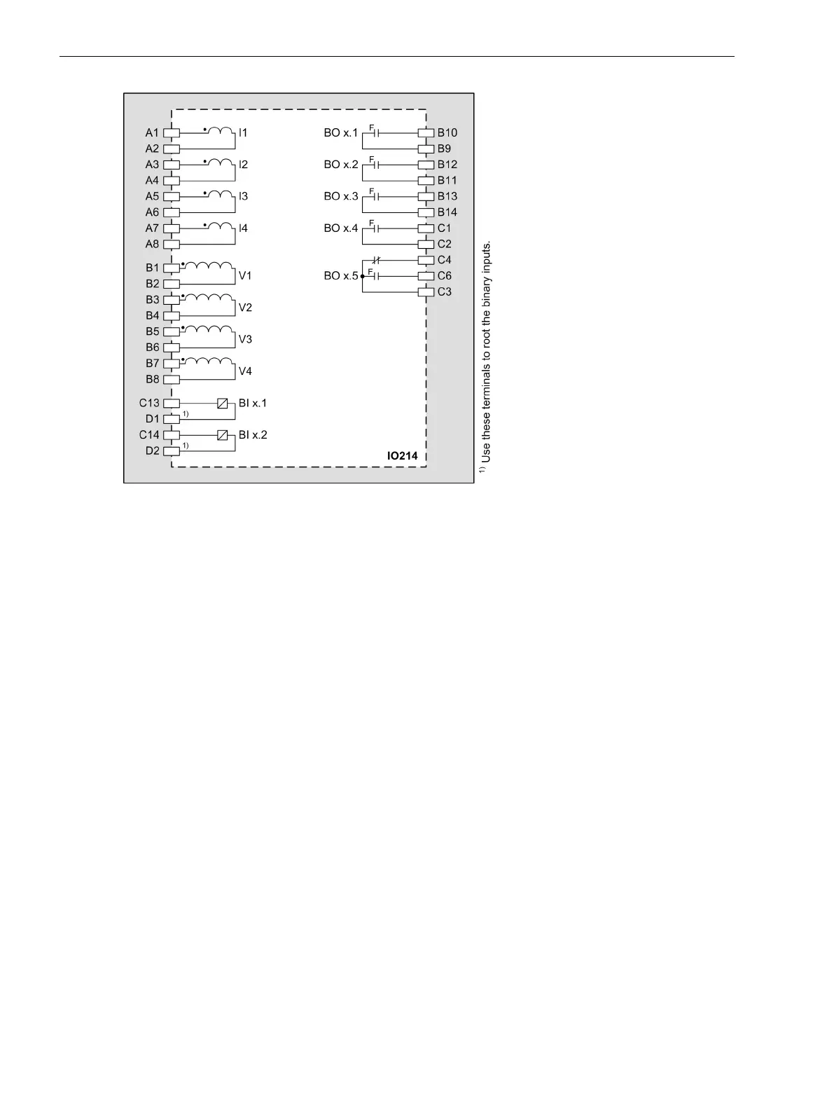
Figure 3-51
IO214 – Connection Diagram
Input and Output Module IO215
Description
This input and output module is used as the base measurement module in all protection devices and bay units.
One device can contain several IO215 input and output modules. The number of IO215 input and output
modules depends on the measured values required. Up to 40 measuring channels are possible for each
SIPROTEC device.
The terminals for the following are located on the input and output module IO215:
•
4 current transformers (optionally protection-class current transformers or instrument transformers)
•
4 voltage transformers for the connection of an isolation amplifier P27000-H1-S011
Connect each phase of the device via this isolation amplifier with capacitive voltage transformers from
the Trench Co. The voltage input is specially designed for a measuring range up to of 7.07 V.
•
8 binary inputs
•
6 binary outputs, of which:
– 4 high-speed make contacts (type F)
– 2 high-speed change-over contacts (type F)
The connections are distributed over:
•
1 x 8-pole current terminal
•
3 x 14-pole voltage terminal
Terminals
The terminal and connection diagram is identical to the input and output module IO202 in the expansion
module.
You can find more information in chapter 3.2.3.2 Terminals, Figure 3-17 and Figure 3-18.
3.2.15
3.2.15.1
3.2.15.2
Electronic Modules
3.2 Input and Output Modules of the Modular Devices
92 SIPROTEC 5, Hardware Description, Manual
C53000-G5040-C002-C, Edition 10.2017

 Loading...


