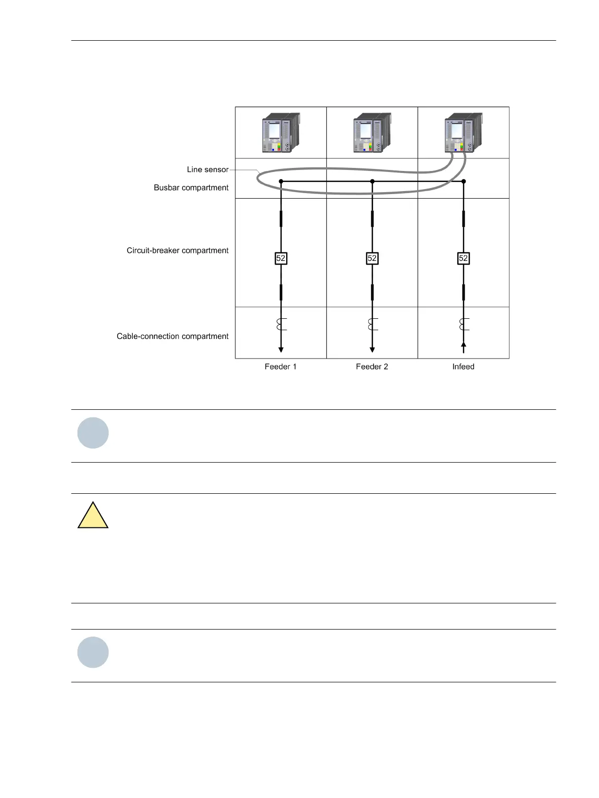
Depending on the possibilities of implementing this in the control cabinet, the line sensor can also be passed
through the breaker compartment and the cable connection compartment of the feeders in addition to the
busbar compartment.
[dw_Liniensensor, 1, en_US]
Figure 5-16
Laying a Line Sensor Along the Busbar
NOTE
Install the arc sensors in the control cabinet in such a way that the relevant sections are not hidden behind
other system components!
Preparing Installation
CAUTION
Exercise caution with laser beams of the optical plug-in modules.
Noncompliance with the safety notes can result in medium-severe or slight injuries.
²
Do not look directly into the fiber-optic terminals of the active optical plug-in modules, not even with
optical devices. The laser beams can damage the eyes.
²
De-energize the device.
NOTE
Laser class 1 is maintained in compliance with EN 60825-1 and EN 60825-2 when using 1 mm polymer
optical fibers.
²
You need 2 holes (10.0 mm in diameter) in the control cabinet for fastening. Siemens recommends a
distance of approx. 10 cm.
Working on the Device
5.4 Arc Sensors for Module: ARC-CD-3FO
SIPROTEC 5, Hardware Description, Manual 177
C53000-G5040-C002-C, Edition 10.2017

 Loading...


