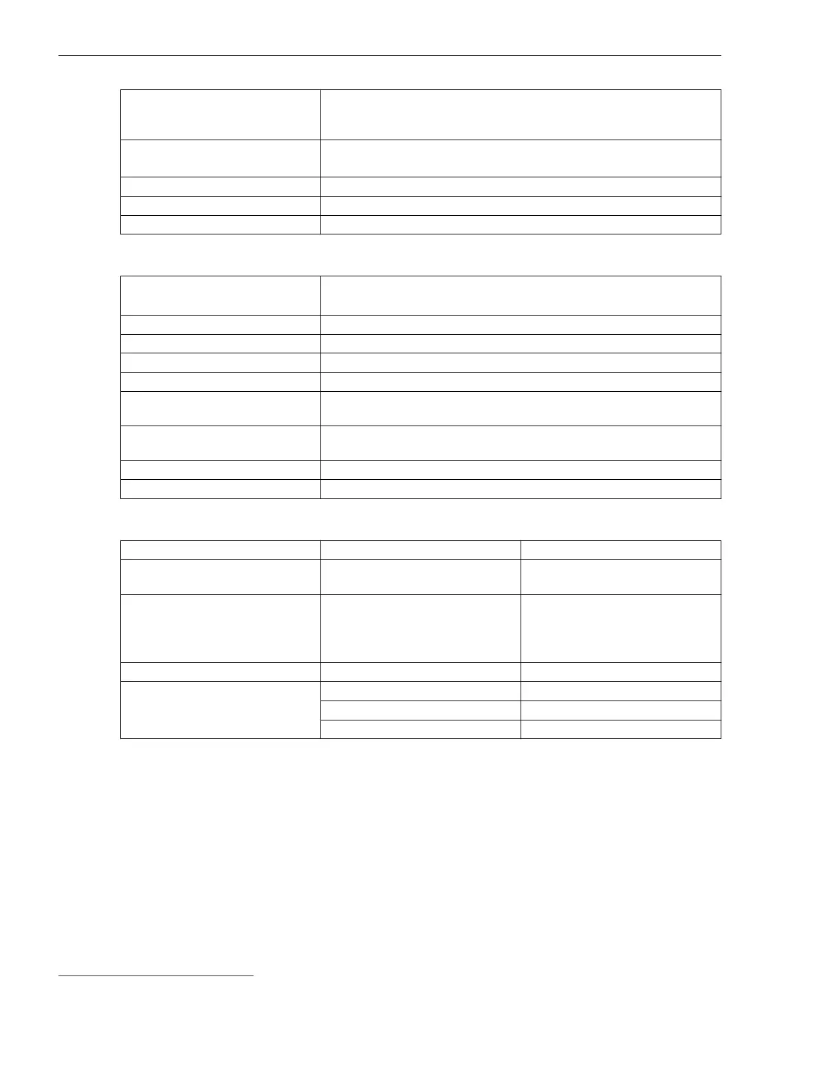
Max. permissible voltage with
respect to ground on the meas-
uring inputs
300 V
Permissible overload DC 20 V continuously
DC 60 V continuously (IO210 MT3 terminal point C9)
Measurement repetition 62.5 μs
Insulation class IO210 ELV (Extra Low Voltage) (acc. to IEC 60255-27)
Insulation class IO212 SELV (acc. to IEC 60255-27)
Table 6-2 High-Speed Measuring-Transducer Inputs, Current
Differential current input channels
IO210: 4
5
IO212: 8
6
Measuring range DC -20 mA to +20 mA
Fault < 0.5 % of the measuring range
Input impedance, current 12 Ω
Conversion principle Delta-sigma (16 bit)
Permissible potential difference
between channels
DC 3.5 kV
Galvanic separation from ground/
housing
DC 3.5 kV
Permissible current overload DC 100 mA continuously
Measurement repetition 62.5 μs
Temperature Inputs
Settings
Value Note
Insulation class PELV (Protective Extra Low Voltage)
(acc. to IEC 60255-27)
–
Measurement mode
•
Pt 100 Ω
•
Ni 100 Ω
•
Ni 120 Ω
3-wire connection, shielded cables
–
Connector type 16-pin, 17-pin terminal spring –
Temperature measuring range -65 °C to +710 °C For PT100
-50 °C to +250 °C For NI100
-50 °C to +250 °C For NI120
5
The IO210 has 4 high-speed measuring-transducer inputs. They can be used either as a voltage or current input.
6
The IO212 has 8 high-speed measuring-transducer inputs. They can be used either as a voltage or current input.
Technical Data
6.1 Analog Inputs
192 SIPROTEC 5, Hardware Description, Manual
C53000-G5040-C002-C, Edition 10.2017

 Loading...


