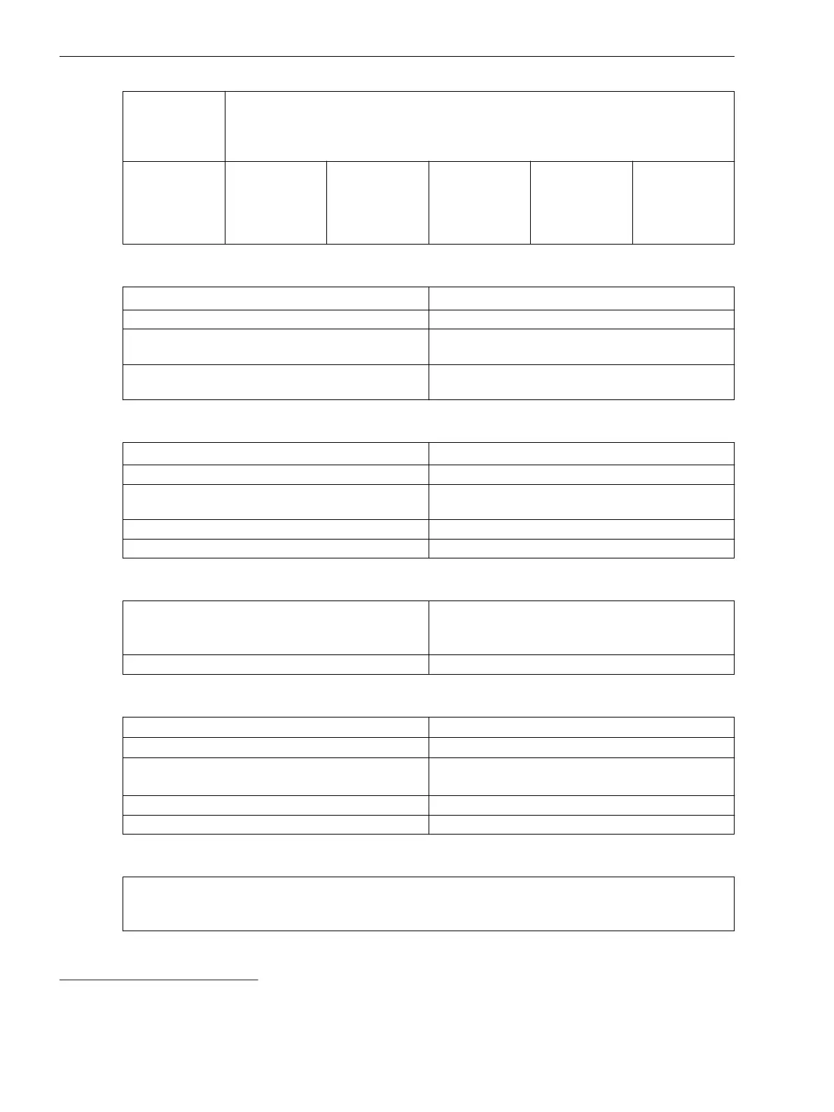
Type of
Construction
(Maximum
Dimensions)
Width over all x Height over all x Depth
14
(in Inches)
Surface-
mounted device
with detached
on-site operation
panel
150 mm x
314 mm x
230 mm (5.91 x
12.36 x 9.06)
225 mm x
314 mm x
230 mm (8.86 x
12.36 x 9.06)
300 mm x
314 mm x
230 mm (11.81
x 12.36 x 9.06)
375 mm x
314 mm x
230 mm (14.76
x 12.36 x 9.06)
450 mm x
314 mm x
230 mm (17.72
x 12.36 x 9.06)
Expansion Module Dimensions
Type of Construction (Maximum Dimensions)
Width x Height x Depth
15
(in Inches)
Flush-mounting device 75 mm x 268 mm x 229 mm (2.95 x 10.55 x 9.02)
Surface-mounted device with integrated on-site oper-
ation panel
75 mm x 314 mm x 337 mm (2.95 x 12.36 x 13.27)
Surface-mounted device with detached on-site opera-
tion panel
75 mm x 314 mm x 230 mm (2.95 x 12.36 x 9.06)
Plug-In Module Dimensions
Type of Construction (Maximum Dimensions) Width x Height x Depth (in Inches)
USART-Ax-xEL, ETH-Bx-xEL 61 mm x 45 mm x 120.5 mm (2.4 x 1.77 x 4.74)
USART-Ax-xFO, ETH-Bx-xFO (without protection
cover)
61 mm x 45 mm x 132.5 mm (2.4 x 1.77 x 5.22)
ANAI-CA-4EL 61 mm x 45 mm x 119.5 mm (2.4 x 1.77 x 4.7)
ARC-CD-3FO 61 mm x 45 mm x 120.5 mm (2.4 x 1.77 x 4.74)
Minimum Bending Radii of the Connecting Cables Between the On-Site Operation Panel and the Base Module
Fiber-optic cable
R = 50 mm
Pay attention to the length of the cable protection
sleeve, which you must also include in calculations.
D-Sub cable R = 50 mm (minimum bending radius)
Degree of Protection According to IEC 60529
For equipment in the surface-mounting housing
IP54
16
for front
For equipment in the flush-mounting housing
IP54
16
for front
For operator protection (back side) IP2x for current terminal (installed)
IP2x for voltage terminal (installed)
Degree of pollution, IEC 60255-27 2
Maximum altitude above sea level 2000 m (6561.68 ft)
UL Note
Type 1 if mounted into a door or front cover of an enclosure.
When expanding the device with the 2nd device row, then they must be mounted completely inside an
enclosure.
14
Width and depth rounded to whole numbers in mm
15
Width and depth rounded to whole numbers in mm
16
The provided plug-in label must be used for expansion modules with LEDs.
Technical Data
6.13 Design Data
212 SIPROTEC 5, Hardware Description, Manual
C53000-G5040-C002-C, Edition 10.2017

 Loading...


