[le_rear expansion module, 1, --_--]
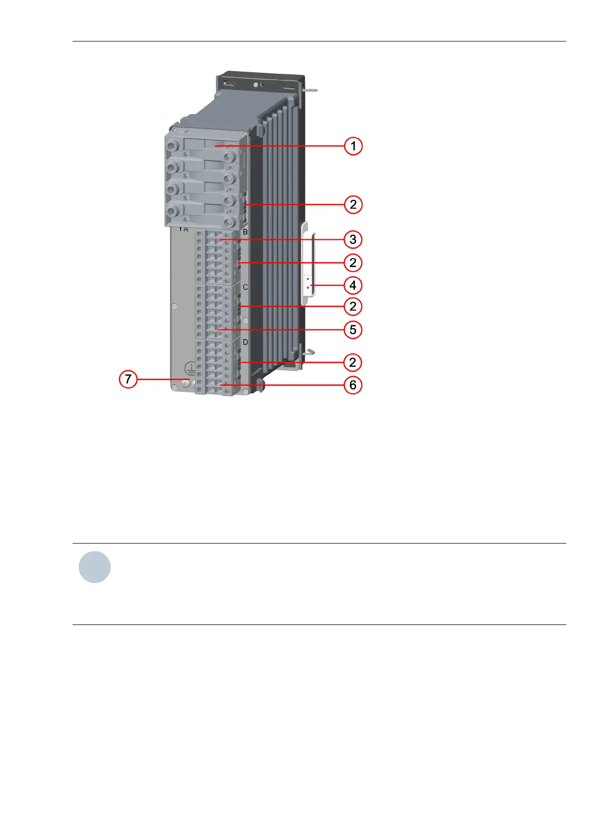
Figure 2-7
Rear View of the Expansion Module
(1) Current terminal xA
(2) Spring clip
(3) Voltage terminal xB
(4) Bus terminal to the base module
(5) Voltage terminal xC
(6) Voltage terminal xD
(7) Protective grounding terminal
NOTE
These modules can be installed in the 1st and 2nd device rows. x corresponds to the slot in the 19-inch
rack.
Possible values in the 1st device row: x = 3, 4, 5, or 6
Possible values in the 2nd device row: x = 8, 9, 10, 11 or 12
Forms of Devices and On-Site Operation Panels
2.1 Flush-Mounting Devices
SIPROTEC 5, Hardware Description, Manual 25
C53000-G5040-C002-C, Edition 10.2017

 Loading...


