Functions
2.9 Frequency Protection 81 (Optional)
SIPROTEC, 7SD80, Manual
E50417-G1140-C474-A1, Release date 09.2011
137
• Address 3622 81-3 PICKUP pickup value for frequency element f3 at f
N
= 50 Hz,
Address 3623 81-3 PICKUP pickup value for frequency element f3 at f
N
= 60 Hz,
Address 3624 81-3 DELAY trip delay for frequency element f3;
• Address 3632 81-4 PICKUP pickup value for frequency element f4 at f
N
= 50 Hz,
Address 3633 81-4 PICKUP pickup value for frequency element f4 at f
N
= 60 Hz,
Address 3634 81-4 DELAY trip delay for frequency element f4;
The set times are additional time delays not including the operating times (measuring time, dropout time) of the
protective function.
If underfrequency protection is used for load shedding purposes, then the frequency settings relative to other
feeder relays are generally based on the priority of the customers served by the protective relay. Normally, load
shedding requires a frequency / time grading that takes into account the importance of the consumers or con-
sumer groups.
In interconnected networks, frequency deviations may also be caused by power swings. Depending on the
power swing frequency, the mounting location of the device and the setting of the frequency elements, it is rec-
ommended to block the entire frequency protection function or single elements once a power swing has been
detected. The time delays must then be coordinated thus that a power swing is detected before the frequency
protection trips.
Further application examples exist in the field of power stations. The frequency values to be set mainly depend
on the specifications of the power system/power station operator. In this context, the underfrequency protection
also ensures the power station’s own demand by disconnecting it from the power system in time. The turbo
regulator regulates the machine set to the nominal speed. Consequently, the station's own demands can be
continuously supplied at nominal frequency.
Since the dropout threshold is 20 MHz below or above the trip frequency, the resulting „minimum“ trip frequency
is 30 MHz above or below the nominal frequency.
A frequency increase can, for example, occur due to a load shedding or malfunction of the speed regulation
(e.g. in a stand-alone system). In this way, the frequency protection can, for example, be used as overspeed
protection.
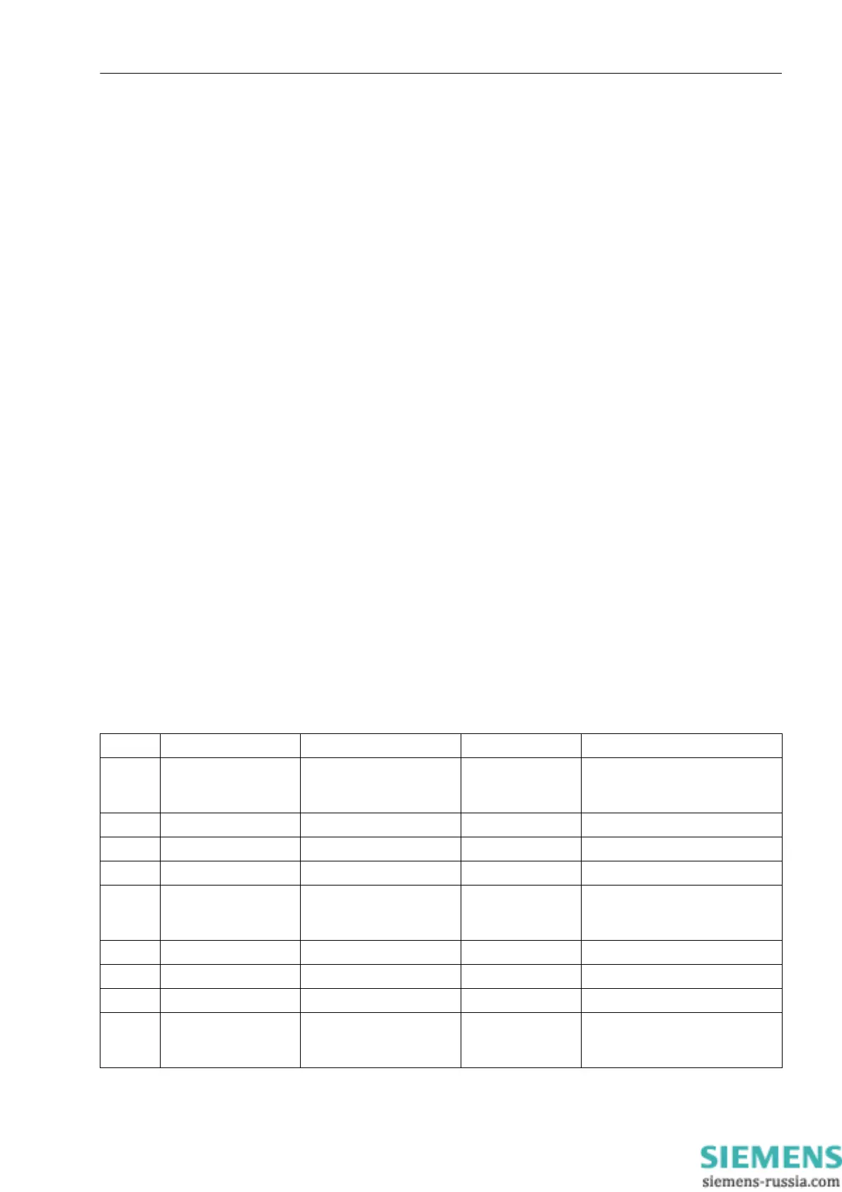
2.9.3 Settings
Addr. Parameter Setting Options Default Setting Comments
3601 81 O/U FREQ. f1 ON: Alarm only
ON: with Trip
OFF
ON: Alarm only 81 Over/Under Frequency Prot.
element f1
3602 81-1 PICKUP 45.50 .. 54.50 Hz 49.50 Hz 81-1 Pickup
3603 81-1 PICKUP 55.50 .. 64.50 Hz 59.50 Hz 81-1 Pickup
3604 81-1 DELAY 0.00 .. 600.00 sec 60.00 sec 81-1 Time Delay
3611 81 O/U FREQ. f2 ON: Alarm only
ON: with Trip
OFF
ON: Alarm only 81 Over/Under Frequency Prot.
element f2
3612 81-2 PICKUP 45.50 .. 54.50 Hz 49.00 Hz 81-2 Pickup
3613 81-2 PICKUP 55.50 .. 64.50 Hz 57.00 Hz 81-2 Pickup
3614 81-2 DELAY 0.00 .. 600.00 sec 30.00 sec 81-2 Time Delay
3621 81 O/U FREQ. f3 ON: Alarm only
ON: with Trip
OFF
ON: Alarm only 81 Over/Under Frequency Prot.
element f3

 Loading...


