Mounting and Commissioning
3.3 Commissioning
SIPROTEC, 7SD80, Manual
E50417-G1140-C474-A1, Release date 09.2011
259
3.3.1 Test Mode and Transmission Block
Activation and Deactivation
If the device is connected to a central or main computer system via the SCADA interface, then the information
that is transmitted can be influenced. This is only possible with some of the protocols available (see Table „Pro-
tocol-dependent functions“ in the Appendix A.6).
If the test mode is switched on, the messages sent by a SIPROTEC 4 device to the main system has an ad-
ditional test bit. This bit allows the messages to be recognized as not resulting from actual faults. Furthermore,
it can be determined by activating the transmission block that no annunciations are transmitted via the system
interface during test mode.
The SIPROTEC 4 System Manual describes in detail how to activate and deactivate the test mode and blocked
data transmission. Please note that when DIGSI is being used for device editing, the program must be in the
online operating mode for the test features to be used.
3.3.2 Checking Time Synchronization
If external time synchronization sources are used, the data of the time source (antenna system, time generator)
are checked (see Subsection 4.1.4 under „Time Synchronization“). A correct function (IRIG B, DCF77) is rec-
ognized in such a way that 3 minutes after the startup of the device the clock status is displayed as „synchro-
nized“, accompanied by the message „Alarm Clock OFF“.
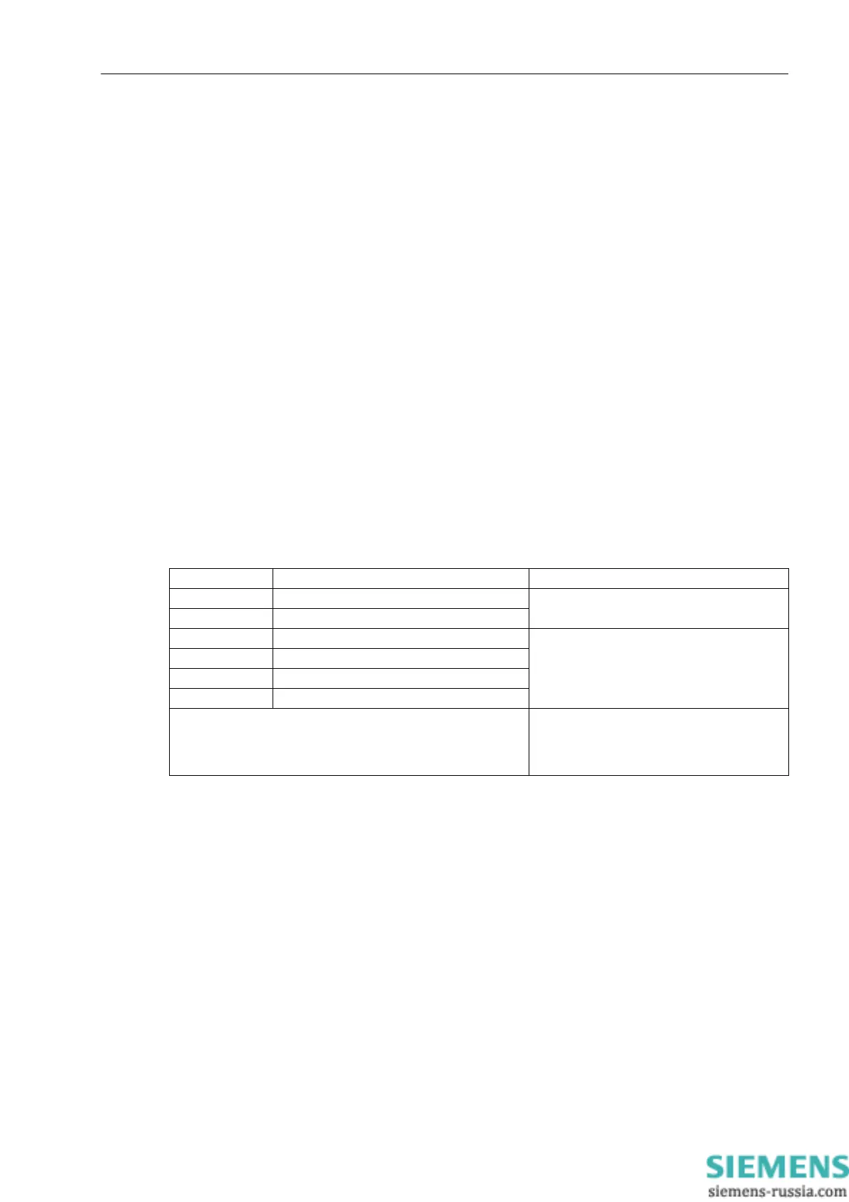
Table 3-4 Time status
If a correct GPS signal is received by a connected GPS receiver, the indication „OFF“ is displayed 3 seconds
after device startup. The pin assignment of the time synchronization interface is indicated in the above table
„Assignment of the port B sockets“.
No. Status text Status
1 – – – – – – – –
synchronized
2 – – – – – – ST
3 – – – – ER – –
not synchronized
4 – – – – ER ST
5 – – NS ER – –
6 – – NS – – – –
Legend:
– – NS – – – –
– – – – ER – –
– – – – – – ST
time invalid
time fault
summertime

 Loading...


