Functions
2.17 Additional Functions
SIPROTEC, 7SD80, Manual
E50417-G1140-C474-A1, Release date 09.2011
207
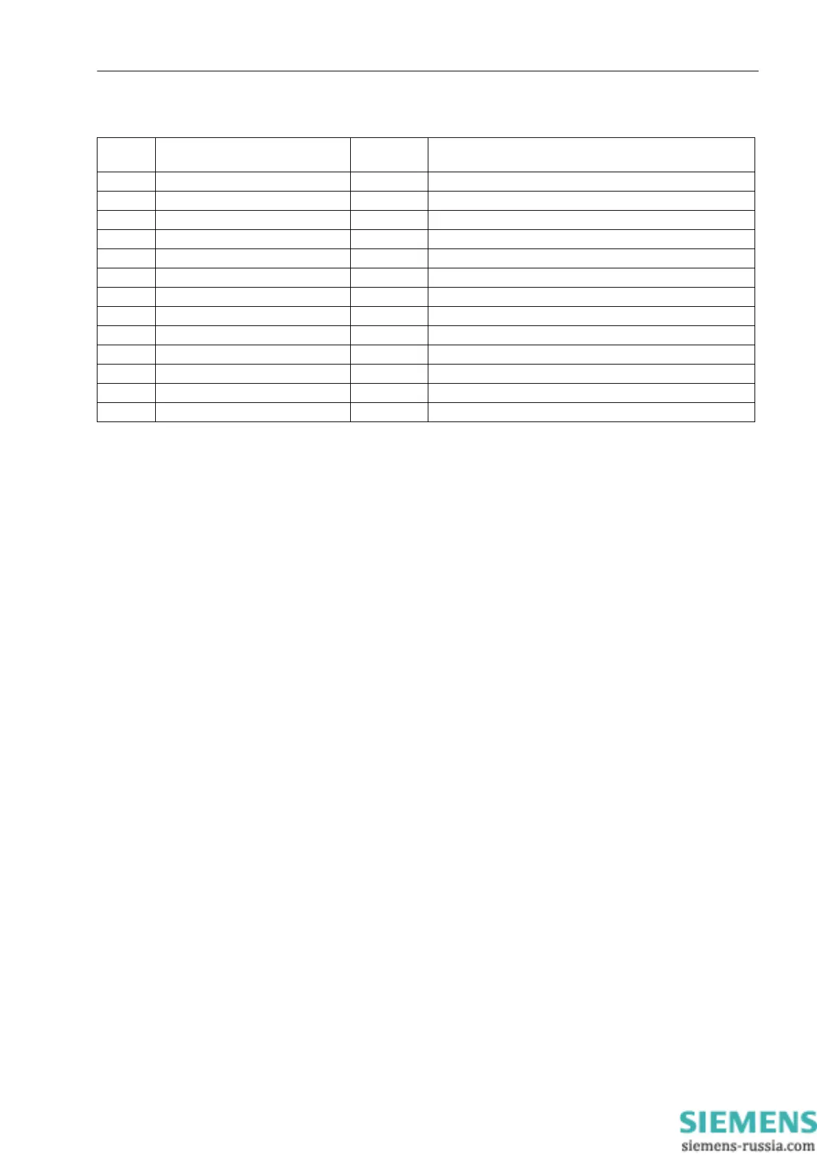
Table 2-12 Measured values constellation for device 1
2.17.6 Min/Max Measurement Setup
Minimum and maximum values are calculated by the 7SD80. Time and date of the last update of the values
can also be read out.
2.17.6.1 Description
Minimum and Maximum Values
The minimum and maximum values for the three phase currents I
x
, the three phase voltages V
x-N
, the phase-
to-phase voltages V
xy
, the positive sequence component I
1
and V
1
, the active power P, reactive power Q, and
apparent power S, the frequency, and the power factor cos ϕ a formed as primary values including the date
and time they were last updated.
The minimum and maximum values of the long-term mean values listed in the next section are also calculated.
The minimum and maximum values can be reset at any time via binary inputs or by using the integrated control
panel or the DIGSI software. Additionally, the reset can be carried out cyclically, starting at a preset point of
time.
2.17.6.2 Setting Notes
Minimum and Maximum Values
The minimum and maximum values can be reset automatically at a programmable point in time. This feature
can be activated by setting address 2811 MinMax cycRESET to YES.
At address 2812 MiMa RESET TIME you can define the point of time when resetting takes place (minute of
the day).
Address 2813 MiMa RESETCYCLE allows you to define the resetting cycle (in days).
At address 2814 MinMaxRES.START you can define when the cyclic process of forming the minimum and
maximum values begins (in days, counted from the time of parameterization).
No. Information Type of In-
formation
Comments
7761 „Relay ID“ MV Device address of the device
7762 „I A_opN=“ MV IA (% of nominal operational current)
7763 „ΦI A=“ MV Angle IA_remote <-> IA_local
7764 „I B_opN=“ MV IB (% of nominal operational current)
7765 „ΦI B=“ MV Angle IB_remote <-> IB_local
7766 „I C_opN=“ MV IC (% of nominal operational current)
7767 „ΦI C=“ MV Angle IC_remote <-> IC_local
7769 „V A_opN=“ MV VA (% of nominal operational voltage)
7770 „ΦV A=“ MV Angle VA_remote <-> VA_local
7771 „V B_opN=“ MV VB (% of nominal operational voltage)
7772 „ΦV C=“ MV Angle VB_remote <-> VB_local
7773 „V C_opN=“ MV VC (% of nominal operational voltage)
7774 „ΦV C=“ MV Angle VC_remote <-> VC_local

 Loading...


