Functions
2.3 Breaker Intertrip and Remote Tripping
SIPROTEC, 7SD80, Manual
E50417-G1140-C474-A1, Release date 09.2011
77
The setting times depend on the individual case of application. A delay is necessary if the external control signal
originates from a disturbed source and a restraint seems appropriate. Of course, the control signal has to be
longer than the delay for the signal to be effective. If the signal is processed externally at the receiving end, a
prolongation time might become necessary for the transmitting end so that the reaction desired at the receiving
end can be executed reliably.
Release Thresholds
Before the release for tripping is given, the phase and ground currents must exceed settable thresholds. You
can set these thresholds at the following addresses:
• 1305 85 DT Iph rel. for the minimum phase current
• 1306 85 DT 3I0 rel. for the minimum ground current 3I0
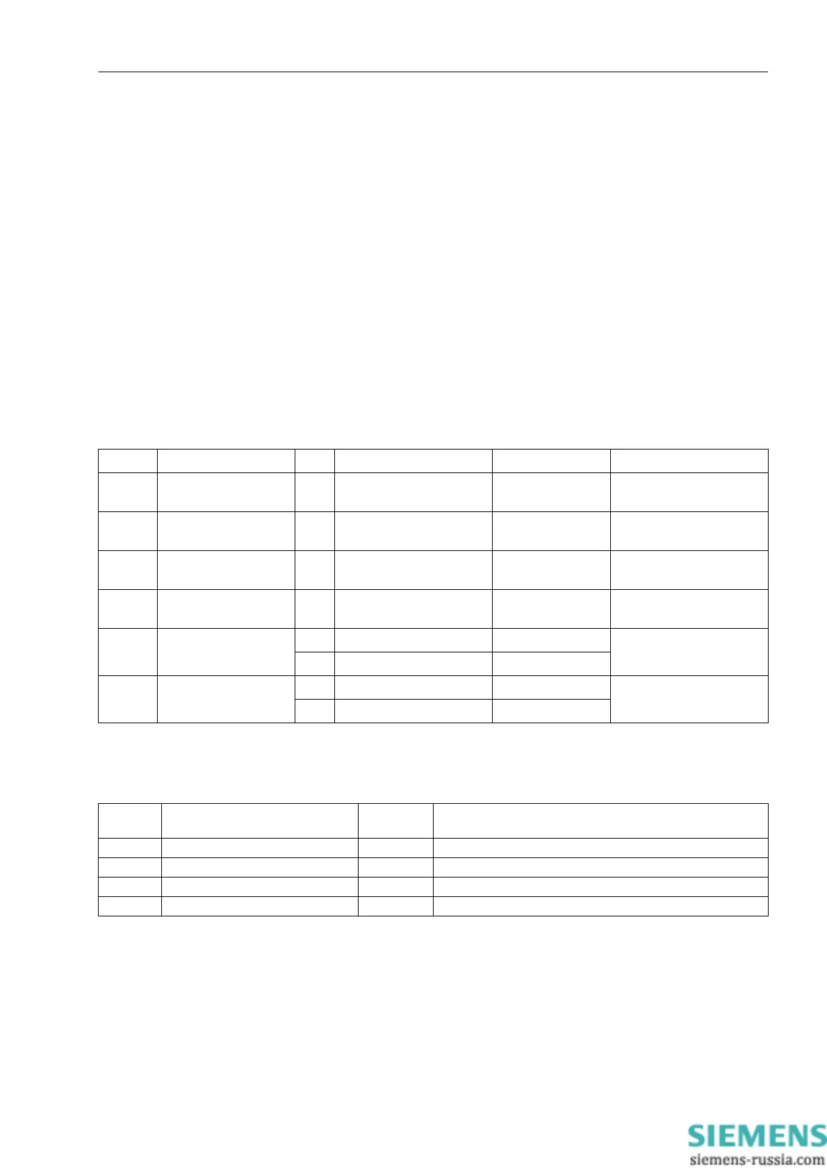
2.3.3 Settings
The table indicates region-specific default settings. Column C (configuration) indicates the corresponding sec-
ondary nominal current of the current transformer.
2.3.4 Information List
Addr. Parameter C Setting Options Default Setting Comments
1301 85 DT: SEND YES
NO
YES 85 DT: State of transm.the
intertrip cmd
1302 85 DT: RECEIVE Alarm only
Trip
Trip 85 DT: React.if intertrip
cmd is receiv.
1303 85 DT: TD-BI 0.00 .. 30.00 sec 0.00 sec 85 DT: Delay for intertrip
via bin.input
1304 85 DT:T-PROL BI 0.00 .. 30.00 sec 0.00 sec 85 DT: Prol. for intertrip via
bin.input
1305 85 DT Iph rel. 1A 0.0 .. 25.0 A; ∞ 0.0 A 85 DT minimal Phase
Current to rel. trip
5A 0.0 .. 125.0 A; ∞ 0.0 A
1306 85 DT 3I0 rel. 1A 0.0 .. 25.0 A; ∞ 0.0 A 85 DT minimal 3I0 Current
to rel. trip
5A 0.0 .. 125.0 A; ∞ 0.0 A
No. Information Type of In-
formation
Comments
3504 >85 DT 3pol SP >86 DT: >Intertrip 3 pole signal input
3517 85 DT Gen. TRIP OUT 85 DT: General TRIP
17525 85 DT rec.3pole OUT 85 DT: Received 3pole
17526 85 DT sen.3pole OUT 85 DT: Sending 3pole

 Loading...


