Functions
2.1 General
SIPROTEC, 7SD80, Manual
E50417-G1140-C474-A1, Release date 09.2011
50
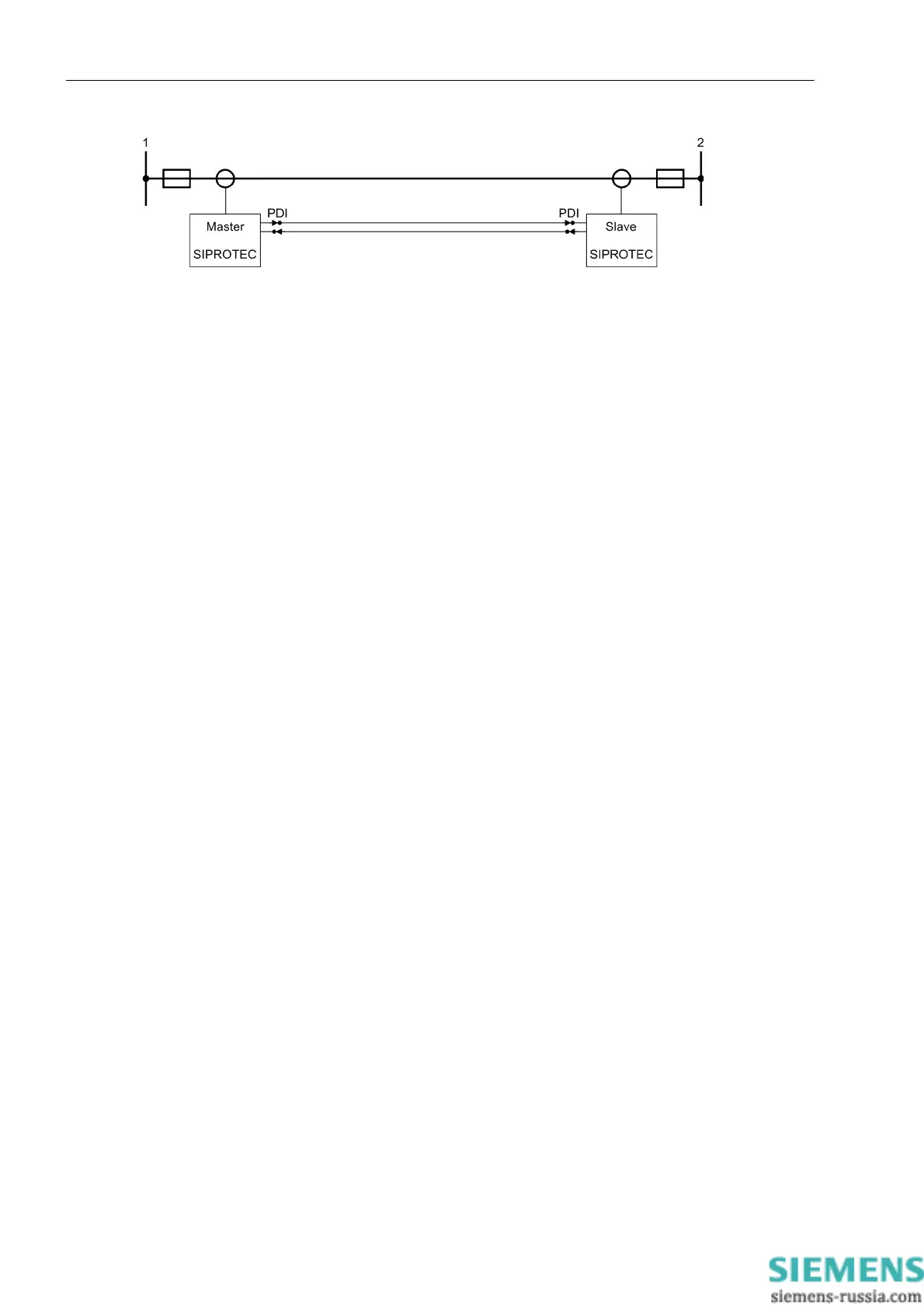
Figure 2-3 Connecting 2 7SD80 devices via protection data interfaces
Communication Failure
The communication is continuously monitored by the devices. Single faulty data telegrams are not a direct risk
if they occur only occasionally. They are recognized and counted in the device which detects the disturbance
and can be read out as statistical information.
If several faulty or no telegrams are received, this is considered a communication disturbance. A correspond-
ing indication is issued.
2.1.8.2 Setting Notes
General
The protection interfaces connect the devices via optical fiber or copper cables. The communication is perma-
nently monitored by the devices. Address 4510 TD-DATA DISTURB defines after which time delay the user is
informed about a faulty or missing telegram.
Once a fault has been detected in the protection interface communication, the time at address 4512 Td
ResetRemote is started for resetting the remote signals. Please note that only the time of the device whose
remote end has failed is effective.
Protection Interface Optical Fiber
If you use an optical fiber connection, switch it ON or OFF at address 4501 PDI FO.
Address 4502 PDI FO TER allows you to enter the permissible maximum fault rate in percent.
At address 4503 PDI FO level you can define the minimum receiving level.
Notes on the settings are given in the Technical Data.
Protection Interface Copper Cable Cu
If you use a copper cable connected to the voltage terminals of the device, switch it ON or OFF at address 4601
PDI Cu.
Address 4602 PDI Cu TER allows you to enter the permissible maximum fault rate in percent.
At address 4604 PDI Cu MAX ATT you can set the maximum attenuation.
At address 4605 PDI Cu S/N you can define the minimum signal/noise ratio.
At address 4603 PDI Cu mode you can specify the transmission parameters.
Notes on the settings are given in the Technical Data.

 Loading...


