Home
Siemens
Protection Device
SIPROTEC 7SD80
Siemens SIPROTEC 7SD80 User Manual
5
of 1
of 1 rating
416 pages
Give review
Manual
Specs
To Next Page
To Next Page
To Previous Page
To Previous Page
Loading...
Functions
2.19 Notes on Device Operatio
n
SIPROTEC, 7SD80, Manual
E50417-G1140-C474-A1, Release date 09.2011
230
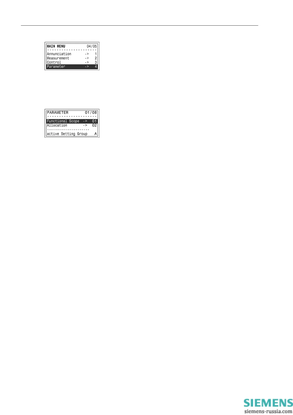
Figure
2-89
Inverse representation of the cu
rrent selection
In part, the sixth line is used
for repres
enting e.g. the active parameter group.
Figure
2-90
Representation of the active parameter group (line 6)
â–
229
231
Table of Contents
Default Chapter
3
Functions
3
Technical Data
4
Table of Contents
9
1 Introduction
17
Overall Operation
18
Application Scope
21
Characteristics
23
2 Functions
27
General
28
Functional Scope
28
Description
28
Setting Notes
29
Settings
31
Device, General Settings
33
Description
33
Setting Notes
34
Settings
34
Information List
35
General Power System Data (Power System Data 1)
37
Setting Notes
37
Settings
40
Oscillographic Fault Records
41
Description
41
Setting Notes
41
Settings
42
Information List
42
Change Group
43
Description
43
Setting Notes
43
Settings
43
Information List
44
General Protection Data (Power System Data 2)
44
Setting Notes
44
Settings
47
Information List
48
EN100-Modul 1
49
Description
49
Information List
49
Protection Interface
49
Setting Notes
50
Settings
51
Information List
51
Phase Comparison Protection and Ground Differential Protection
52
Differential Topology
52
Setting Notes
52
Settings
52
Information List
52
Phase Comparison Protection
53
Description
53
Setting Notes
57
Ground Current Differential Protection in Grounded Systems
59
Description
59
Setting Notes
62
Ground Fault Differential Protection in Resonant-Grounded/Isolated Systems
63
Description
63
Setting Notes
66
Differential Protection Pickup Logic and Tripping Logic
67
Description
67
Differential Protection
68
Settings
69
Information List
70
Differential Protection Test and Commissioning
71
Differential Protection Test
71
Differential Protection Commissioning
73
Breaker Intertrip and Remote Tripping
75
Description
75
Setting Notes
76
Settings
77
Information List
77
Backup Overcurrent
78
Operating Modes
78
Non-Directional Overcurrent Protection
78
Directional Overcurrent Protection
83
Setting Notes
89
Settings
93
Information List
96
Inrush Restraint
98
Description
98
Setting Notes
99
Settings
100
Information List
100
Circuit-Breaker Failure Protection 50BF
101
Description
101
Setting Notes
108
Settings
110
Information List
111
Thermal Overload Protection 49
112
Method of Operation
112
Setting Notes
113
Settings
115
Information List
115
Undervoltage and Overvoltage Protection 27/59 (Optional)
116
Overvoltage Protection (ANSI 59)
116
Undervoltage Protection (ANSI 27)
121
Setting Notes
124
Settings
128
Information List
130
Frequency Protection 81 (Optional)
133
Description
133
Setting Notes
136
Settings
137
Information List
138
Direct Local Trip
139
Description
139
Setting Notes
140
Settings
140
Information List
140
Automatic Reclosure Function 79 (Optional)
141
Description
141
Setting Notes
148
Settings
152
Information List
154
Circuit-Breaker Test
155
CB Close Detection
155
Circuit-Breaker Position Detection
158
Circuit-Breaker Test
159
Information List
160
Direct Remote Trip and Transmission of Binary Information
161
Description
161
Information List
162
Monitoring Functions
163
Measurement Supervision
163
Hardware Monitoring
163
Software Monitoring
165
External Transformer Circuits
165
Fault Responses
174
Setting Notes
176
Settings
177
Information List
178
74TC Trip Circuit Supervision
179
Method of Operation
179
Setting Notes
182
Settings
182
Information List
182
Flexible Protection Functions
183
Description
183
Setting Notes
187
Settings
191
Information List
193
Function Control
194
Pickup Logic for the Entire Device
194
Overall Tripping Logic of the Device
195
Additional Functions
199
Indications Processing
199
Leds and Binary Outputs (Output Relays)
199
Information Via Display Field or PC
200
Information to a Control Center
201
Statistics
201
Description
202
Information List
202
Measurement During Operation
203
Description
203
Information List
205
Differential Protection Values
206
Measured Values of the Differential Protection
206
Information List
206
Constellation Measured Values
206
Description
206
Min/Max Measurement Setup
207
Description
207
Setting Notes
207
Settings
208
Information List
208
Demand Measurement Setup
210
Description
210
Setting Notes
210
Settings
210
Information List
211
Set Points (Measured Values)
212
Setting Notes
212
Information List
212
Energy
213
Energy Metering
213
Setting Notes
213
Information List
213
Breaker Control
214
Control Device
214
Description
214
Information List
215
Command Types
216
Description
216
Command Sequence
217
Description
217
Switchgear Interlocking Protection
218
Description
218
Command Logging
228
Description
228
Notes on Device Operation
229
Different Operation
229
3 Mounting and Commissioning
231
Mounting and Connections
232
Configuration Information
232
Hardware Modifications
237
Disassembly
237
Connections of the Current Terminals
241
Connections of the Voltage Terminals
243
Interface Modules
244
Reassembly
247
Installation
248
General
248
Panel Flush Mounting
249
Cubicle Mounting
250
Panel Surface Mounting
251
Checking Connections
252
Checking the Data Connections of the Interfaces
252
Checking the Protection Data Communication
255
Checking the System Connections
256
Commissioning
258
Test Mode and Transmission Block
259
Checking Time Synchronization
259
Testing the System Interface (at Port B)
260
Configuring Communication Modules
262
Checking the Status of Binary Inputs and Outputs
265
Checking the Protection Data Communication
268
Tests for Circuit-Breaker Failure Protection
270
Checking the Instrument Transformer Connections of One Line End
272
Checking the Instrument Transformer Connections of Two Line Ends
277
Checking the Pilot Protection for Internal and External Remote Tripping
277
Testing User-Defined Functions
277
Trip and Close Test with the Circuit Breaker
278
Switching Check for the Configured Equipment
278
Triggering Oscillographic Recording for Test
279
Final Preparation of the Device
280
4 Technical Data
281
General Device Data
282
Analog Inputs
282
Auxiliary Voltage
283
Binary Inputs and Outputs
284
Communication Interfaces
285
Electrical Tests
288
Mechanical Stress Tests
290
Climatic Stress Tests
290
Service Conditions
291
Design
291
UL Certification Conditions
292
Protection Interfaces and Connections
293
Differential Protection Phase Comparison Protection
296
Ground Fault Differential Protection in Grounded Systems
299
Ground Fault Differential Protection in Resonant-Grounded / Isolated Systems
300
Breaker Intertrip and Remote Tripping- Direct Local Trip
301
Time Overcurrent Protection
302
Inrush Current Restraint Breaker Intertrip and Remote Tripping
309
Circuit-Breaker Failure Protection (Optional)
310
Thermal Overload Protection 49
311
Voltage Protection (Optional)
313
Frequency Protection (Optional)
316
Automatic Reclosing (Optional)
317
Transmission of Binary Information and Commands
318
Monitoring Functions
319
Flexible Protection Functions
321
User-Defined Functions (CFC)
324
Additional Functions
328
Dimensions
330
Panel Flush Mounting and Cabinet Flush Mounting (Housing Size 1/6)
330
Panel Surface Mounting (Housing Size 1/6)
331
Bottom View
332
Appendix
333
Ordering Information and Accessories
334
Ordering Information
334
7Sd80 V4.6
334
Accessories
337
A.1.2 Accessories
337
Terminal Assignments
339
Connection Examples
345
A.3 Connection Examples
345
Current Transformer Requirements
348
Current Transformer Ratio
348
Overcurrent Factors
348
Class Conversion
349
Core Balance Current Transformer
349
General
349
Requirements
349
A.4.3 Class Conversion
349
Class Accuracy
350
7 SD80 - Housing for Panel Flush Mounting and Cabinet Flush Mounting and for Panel Surface Mounting
339
A.2 Terminal Assignments
339
Default Settings
351
Leds
351
Binary Input
351
A.5 Default Settings
351
A.5.3 Binary Output
352
Binary Output
352
Function Keys
352
A.5.5 Default Display
353
Default Display
353
Pre-Defined CFC Charts
356
Protocol-Dependent Functions
357
A.7 Functional Scope
358
Functional Scope
358
A.8 Settings
360
Settings
360
A.9 Information List
371
Information List
371
A.10 Group Alarms
393
Group Alarms
393
A.11 Measured Values
394
Measured Values
394
Literature
399
Glossary
401
Index
413
5
Based on 1 rating
Ask a question
Give review
Questions and Answers:
Need help?
Do you have a question about the Siemens SIPROTEC 7SD80 and is the answer not in the manual?
Ask a question
Siemens SIPROTEC 7SD80 Specifications
General
Brand
Siemens
Model
SIPROTEC 7SD80
Category
Protection Device
Language
English
Related product manuals
Siemens Siprotec 7SD600
170 pages
Siemens SIPROTEC 7SS52
210 pages
Siemens SIPROTEC 7SK80
490 pages
Siemens SIPROTEC 7SJ64
94 pages
Siemens SIPROTEC 7ST61
94 pages
Siemens siprotec 7SA522
606 pages
Siemens SIPROTEC 7SJ531
362 pages
Siemens SIPROTEC easy 7SJ45
81 pages
Siemens SIPROTEC 7UM62
638 pages
Siemens SIPROTEC 7UT612
94 pages
Siemens SIPROTEC 7UT613 series
638 pages
Siemens SIPROTEC 4 7UT6 Series
684 pages