Technical Data
4.17 User-defined Functions (CFC)
SIPROTEC, 7SD80, Manual
E50417-G1140-C474-A1, Release date 09.2011
325
General Limits
NEG Negator X X X X
NOR NOR - Gate X X X X
OR OR - Gate X X X X
REAL_TO_DINT Real after DoubleInt, adapter X X X X
REAL_TO_UINT Real after U-Int, adapter X X X X
RISE_DETECT Rising edge detector X X X X
RS_FF RS- Flipflop – X X X
RS_FF_MEMO Status memory for restart X X X X
SI_GET_STATUS Information status single point
indication, decoder
XX X X
SI_SET_STATUS Single point indication with
status, encoder
XX X X
SQUARE_ROOT Root Extractor X X X X
SR_FF SR- Flipflop – X X X
SR_FF_MEMO Status memory for restart X X X X
ST_AND AND gate with status X X X X
ST_NOT Negator with status X X X X
ST_OR OR gate with status X X X X
SUB Substraction X X X X
TIMER Timer – X X –
TIMER_SHORT Simple timer – X X –
UINT_TO_REAL U-Int to real, adapter X X X X
UPPER_SETPOINT Upper Limit X – – –
X_OR XOR - Gate X X X X
ZERO_POINT Zero Supression X – – –
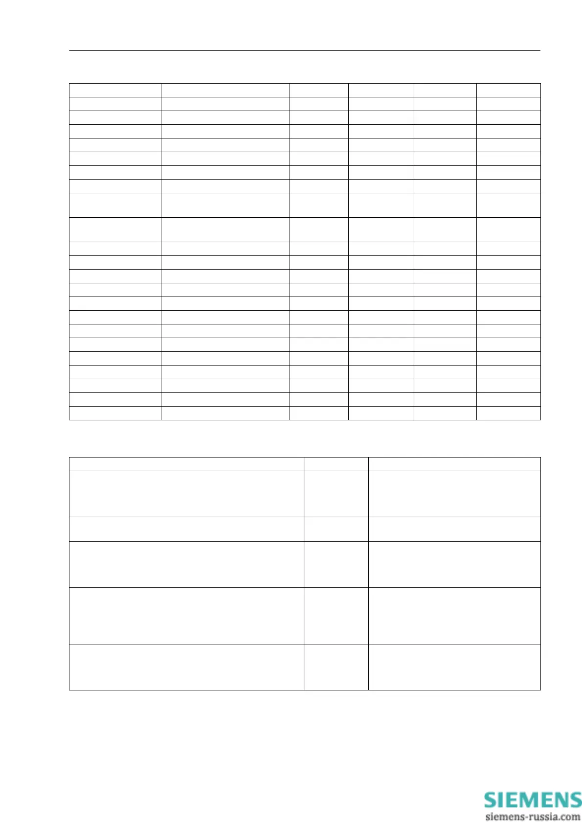
Description Limit Comments
Maximum number of all CFC charts considering all task
levels
32 When the limit is exceeded, an error
message is output by the device. Conse-
quently, the device starts monitoring. The
red ERROR-LED lights up.
Maximum number of all CFC charts considering one task
level
16 Only Error Message
(evolving fault in processing procedure)
Maximum number of all CFC inputs considering all charts 400 When the limit is exceeded, an error
message is output by the device. Conse-
quently, the device starts monitoring. The
red ERROR-LED lights up.
Maximum number of inputs of one chart for each task level
(number of unequal information items of the left border per
task level)
400 Only fault annunciation; here the number of
elements of the left border per task level is
counted. Since the same information is indi-
cated at the border several times, only
unequal information is to be counted.
Maximum number of reset-resistant flipflops
D_FF_MEMO, RS_FF_MEMO, SR_FF_MEMO
350 When the limit is exceeded, a fault indica-
tion is output by the device. Consequently,
the device is put into monitoring mode. The
red ERROR-LED lights up.

 Loading...


