SINAMICS G150
Engineering Information
SINAMICS Engineering Manual – November 2015
Ó Siemens AG
304/528
Maximum output frequency
With SINAMICS G150 cabinet units, the maximum output frequency is limited to 100 Hz or 160 Hz due to the factory-
set pulse frequency of f
Pulse
= 1.25 kHz (current controller clock cycle = 400 μs) or f
Pulse
= 2.00 kHz (current controller
clock cycle = 250 μs). The pulse frequency must be increased if higher output frequencies are to be achieved. Since
the switching losses in the motor-side IGBT inverter increase when the pulse frequency is raised, the output current
must be reduced accordingly.
Permissible output current and maximum output frequency as a function of pulse frequency
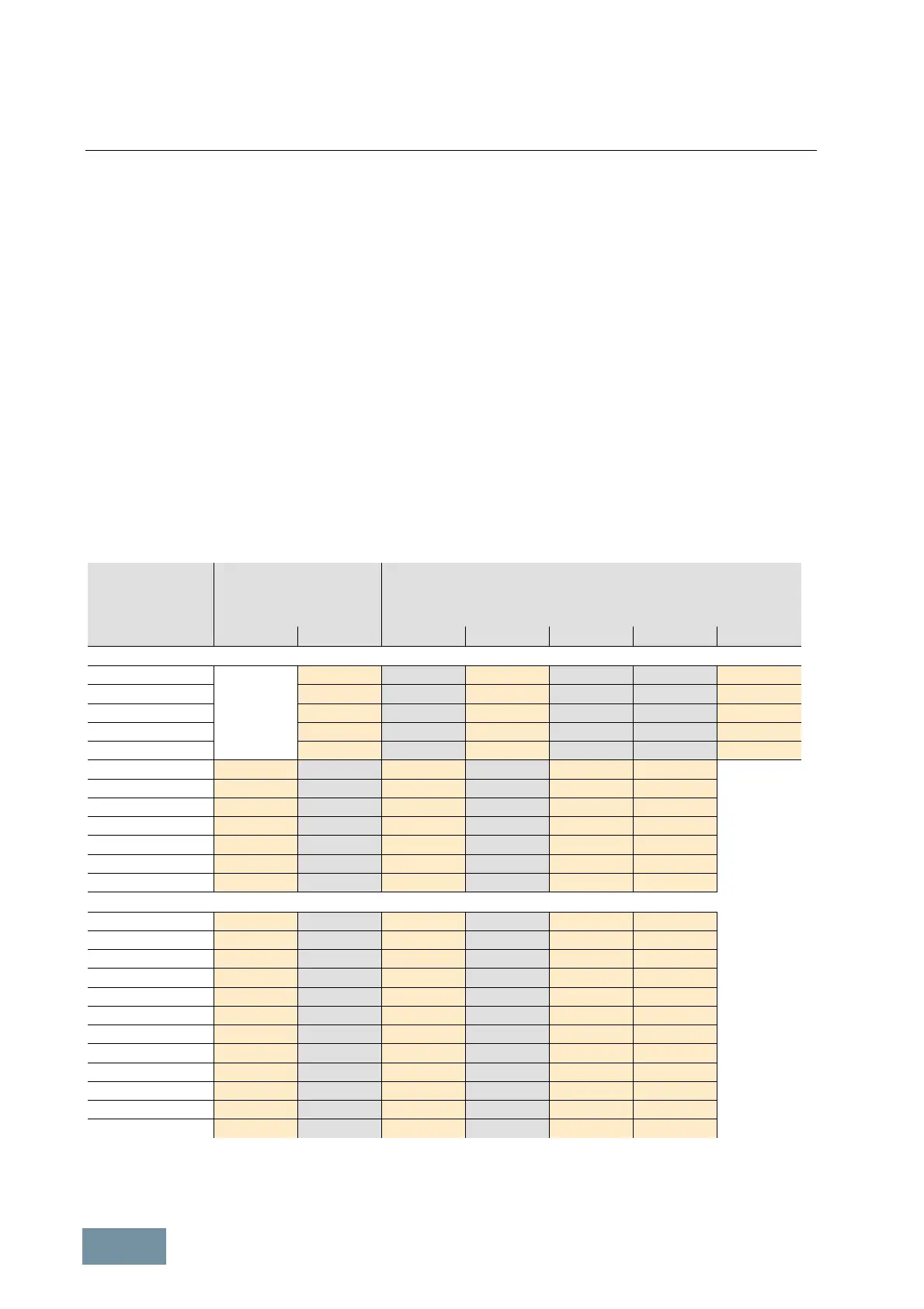
The table below states the rated output currents of SINAMICS G150 converters with the factory-set pulse frequency,
as well as the current derating factors (permissible output currents referred to the rated output current) at higher
pulse frequencies.
The pulse frequencies for the values in the orange boxes can be selected simply by changing a parameter (even
during operation), i.e. they do not necessitate a change to the factory-set current controller clock cycle. The pulse
frequencies for the values in the grey boxes require a change in the factory-set current controller clock cycle and can
therefore be selected only at the commissioning stage. The assignment between current controller clock cycles and
possible pulse frequencies can be found in the List Manual (Parameter List).
Under certain boundary conditions (line voltage at low end of permissible wide-voltage range, low ambient
temperature, restricted speed range), it is possible to partially or completely avoid current derating at pulse
frequencies which are twice as high as the factory setting. Further details can be found in section "Operation of
converters at increased pulse frequency".
Output power
at
400V / 500V / 690 V
Rated output current
or
current derating factor
with pulse frequency of
Current derating factor
with pulse frequency of
1.25 kHz 2.0 kHz 2.5 kHz 4.0 kHz 5.0 kHz 7.5 kHz 8.0 kHz
380 V – 480 V 3AC
110 kW 210 A 95 % 82 % 74 % 54 % 50 %
132 kW 260 A 95 % 83 % 74 % 54 % 50 %
160 kW 310 A 97 % 88 % 78 % 54 % 50 %
200 kW 380 A 96 % 87 % 77 % 54 % 50 %
250 kW 490 A 94 % 78 % 71 % 53 % 50 %
315 kW 605 A 83 % 72 % 64 % 60 % 40 %
400 kW 745 A 83 % 72 % 64 % 60 % 40 %
450 kW 840 A 87 % 79 % 64 % 55 % 40 %
560 kW 985 A 92 % 87 % 70 % 60 % 50 %
630 kW 1120 A
1)
83 % 72 % 64 % 60 % 40 %
710 kW 1380 A
1)
83 % 72 % 64 % 60 % 40 %
900 kW 1560 A
1)
87 % 79 % 64 % 55 % 40 %
500 V – 600 V 3AC
110 kW 175 A 92 % 87 % 70 % 60 % 40 %
132 kW 215 A 92 % 87 % 70 % 60 % 40 %
160 kW 260 A 92 % 88 % 71 % 60 % 40 %
200 kW 330 A 89 % 82 % 65 % 55 % 40 %
250 kW 410 A 89 % 82 % 65 % 55 % 35 %
315 kW 465 A 92 % 87 % 67 % 55 % 35 %
400 kW 575 A 91 % 85 % 64 % 50 % 35 %
500 kW 735 A 87 % 79 % 64 % 55 % 25 %
560 kW 810 A 83 % 72 % 61 % 55 % 35 %
630 kW 860 A
1)
92 % 87 % 67 % 55 % 35 %
710 kW 1070 A
1)
91 % 85 % 64 % 50 % 35 %
1000 kW 1360 A
1)
87 % 79 % 64 % 55 % 25 %
1)
G150 parallel connection / the specified currents represent the total current of all inverter sections
SINAMICS G150: Permissible output current (current derating factor) as a function of pulse frequency
 Loading...


