4.2 Structure
Depending on a customer-specific order, the device comprises different parts.
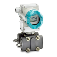
① Cover over buttons and nameplate with general information ⑨ Screw for the cover over the buttons
② Cover (front), optionally with inspection window ⑩ Cover (rear) for electrical terminal compart‐
ment
③ Display (optional) ⑪ Electrical terminal compartment
④ Safety catch (front) ⑫ Safety catch (back)
⑤ Retaining screw for rotation of the enclosure (Page 57) ⑬ Ground terminal
⑥ Process connection ⑭ Nameplate with information on the remote
seal
⑦ Nameplate with approval information ⑮ Blanking plug
⑧ Cable inlet, optionally with cable gland
Figure 4-1 Example
● The electronic housing is made of aluminum die casting or stainless steel precision casting.
● The housing has a removable cover at the front and the back.
● Depending on the device version, the front cover ② may be designed as an inspection
window.
● The cable gland ⑧ to the electrical terminal compartment is at the side; either the left or
right-hand one can be used. The unused opening is closed with a blanking plug ⑮.
● The ground terminal ⑬ is located on the side.
● The electrical terminal compartment ⑪ for the auxiliary power and shield is accessible
when you remove the back cover ⑩.
● The measuring cell with a process connection ⑥ is located in the lower section of the
enclosure.
The measuring cell is prevented from rotating by a retaining screw ⑤.
● Thanks to the modular design of the pressure transmitter, the measuring cell and application
electronics or terminal compartment can be replaced if required.
Description
4.2 Structure
SITRANS P320/P420 (mA/HART)
Operating Instructions, 06/2018, A5E44852162-AA 25
 Loading...


