6.2.2 Connecting the device
Procedure
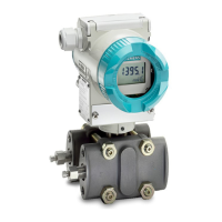
① Feed separator with integrated load ⑥ Safety catch
② Supply voltage ⑦ Process connec‐
tion
③ Cable gland for supply voltage/current output ⑧ Protective conduc‐
tor connector/equi‐
potential bonding
terminal
④ Connecting terminals ⑨ Ground terminal
⑤ Test connector for DC measuring device
Figure 6-2 Example: Electrical connection with feed separator
1. Lead the connecting cable through the cable gland ③.
2. Connect the device to the plant using the existing protective conductor connection ⑧.
Connecting
6.2 Connecting the device
SITRANS P320/P420 (mA/HART)
Operating Instructions, 06/2018, A5E44852162-AA 63
 Loading...


