J3 or J4 = J4 if SWITCH-TO-BATTERY signal is used. Otherwise, J3.
J5 or J6 = J6 if SWITCH-TO-BATTERY signal is used. Otherwise, J5.
Connectors and Connector Pins
PI, P2 and P8 = Do not exist.
P3 = 3-pin connector.
l
P3-1 = PMSI. Normally OV. +24V when trouble in PMS circuit.
l
P3-2 = COIL. Normally OV. +24V during brownout.
l
P3-3 = 24VDC COMMON.
P4 = 4-pin connector.
l
P4-1 = PMSO. Normally OV. +24V when trouble in PMS circuit.
l
P4-2 = COIL. Normally OV. +24V during brownout.
l
P4-3 = 24VDC COMMON.
l
P4-4 = Unused.
P5 = 4-pin connector.
l
P5-1 = +24VDC output from Fuse F2.
l
P5-2 = 24VDC COMMON.
l
P5-3 = Normally +24V. OV when the SWITCH-TO-BATTERY signal is present.
l
P5-4 = Unused.
P6 = 4-pin connector.
l
P6-1 = +24VDC output from Fuse F3.
l
P6-2 = 24VDC COMMON.
l
P6-3 = Normally +24V. OV when the SWITCH-TO-BATTERY signal is present.
l
P6-4 = Unused.
P7 = 2-pin connector.
l
P7-1 = -BATTERY.
l
P7-2 = +BATTERY.
P9 = 2-pin connector.
l
P9-1 = +24V lead to externally mounted capacitor.
l
P9-2 = OV lead to externally mounted capacitor.
Terminal Block TBl
TBI -1 = Transformer Secondary (Red lead).
TBI -2 = Transformer Secondary (Red lead).
TBI -3 = Transformer Secondary, Center Tap (Yellow lead).
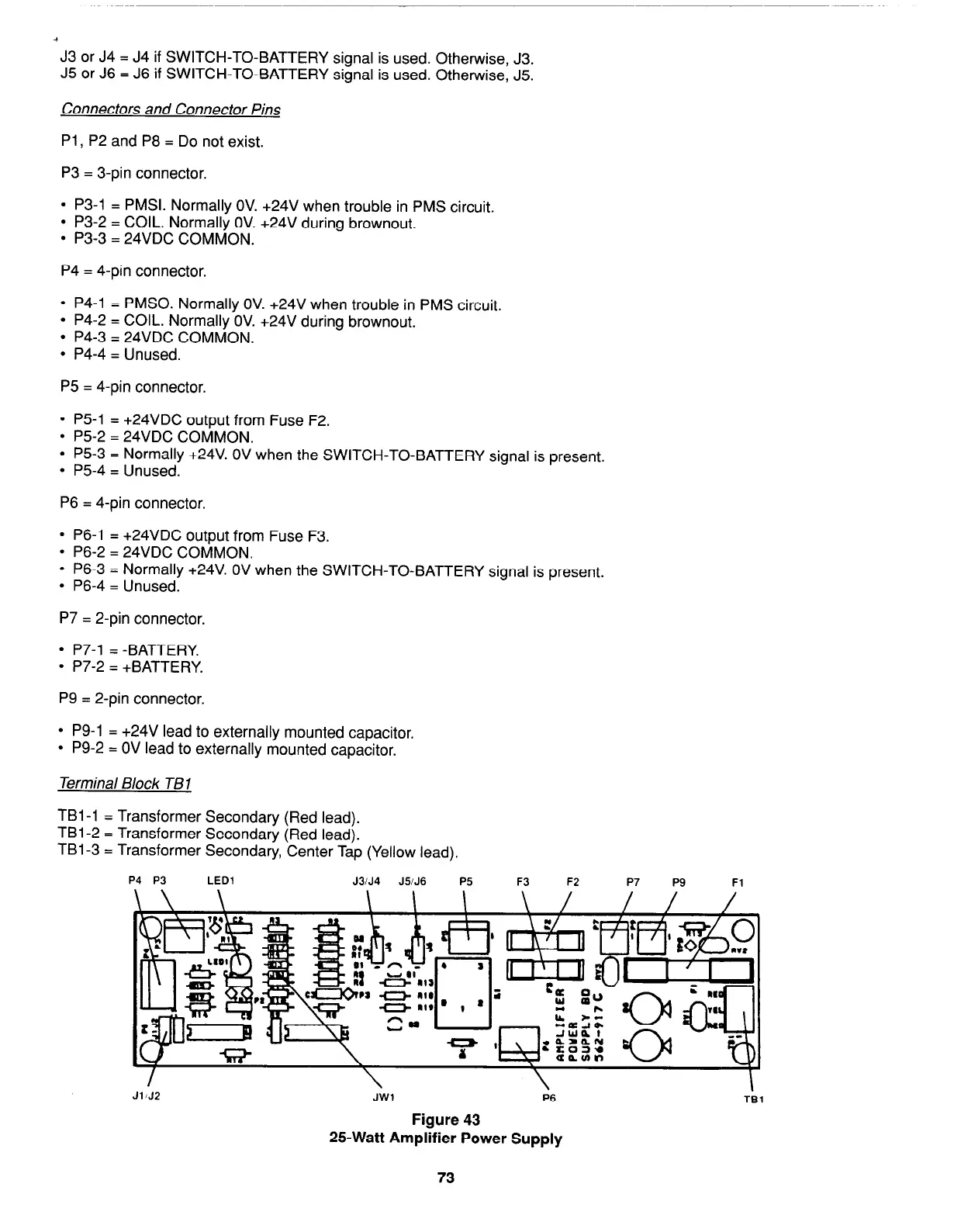
P4 P3 LED1
J3iJ4
J5iJ6
P5 F3 F2
P7
P9 Fl
/
JllJ2
\
\
JW1 P6
Figure 43
25-Watt Amplifier Power Supply
I
TBl
73