31
SKOPE BME-N ActiveCore
Replacement Procedures
Service Manual
The rating label MUST state refrigerant as R290. If the label states a different refrigerant, or
does NOT state a refrigerant, it is not suitable for a hydrocarbon cartridge.
For servicing or transportation, the refrigeration cartridge unplugs and slides out of the cabinet.
Some minor servicing can be performed without removing the refrigeration cartridge.
The model and serial number are both printed on the unit rating/serial number label attached
to the side of the cover.
Specifications for the model are in the following table. Verify the model and basic requirements
before servicing.
Not Cooling
Fault
If a customer reports a “not cooling” fault, and it has been established that the cabinet is not
cooling, follow the procedure on page 56 when making the service visit.
Removing the
Cartridge
Follow the steps below to remove the refrigeration cartridge from the cabinet. Ensure the
cabinet is disconnected from the mains power supply before removing the cartridge (see
page 22).
WARNING
The hydrocarbon cartridge must only be used on a
hydrocarbon-compliant cabinet.
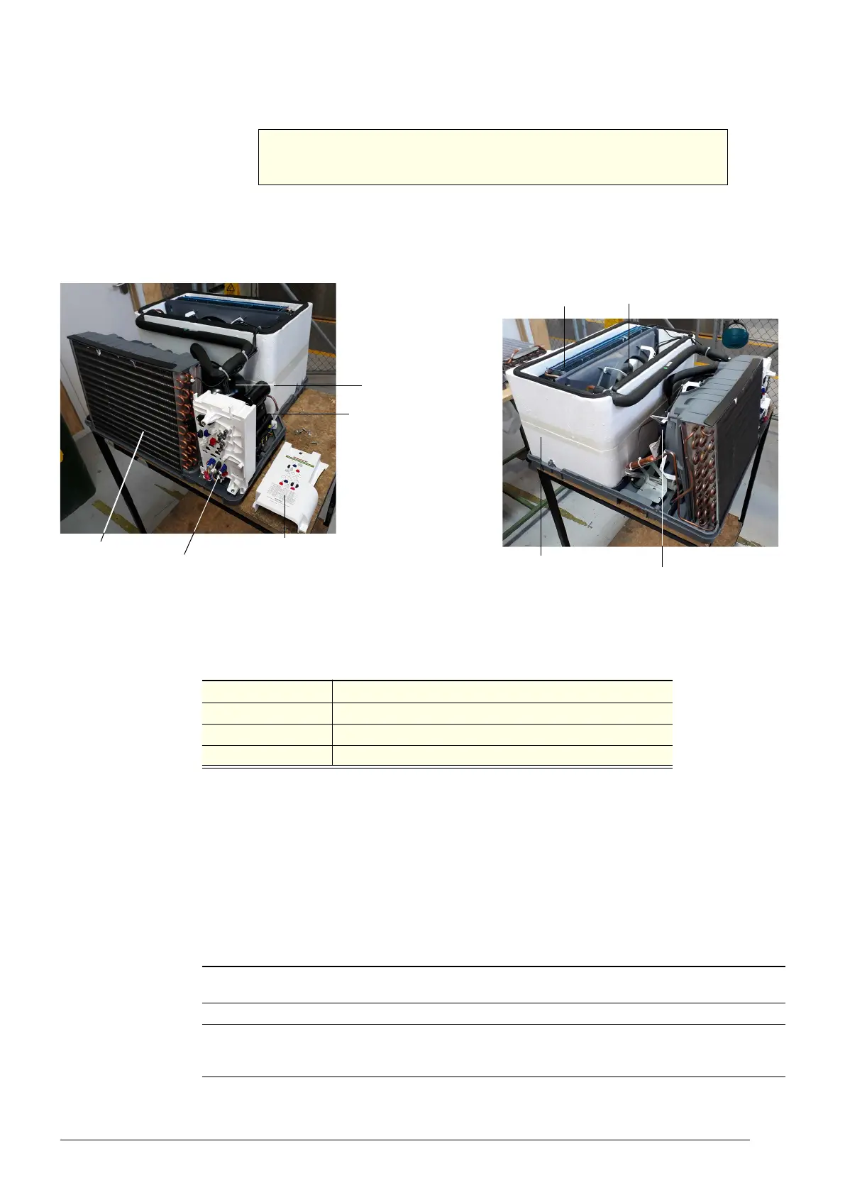
Cartridge electrics box
Evaporator coil
Compressor
electrics
Evaporator fan
Condenser fan
Evaporator tub
Compressor
Condenser coil
Cartridge electrics box cover
Table 7: Cartridge specifications
Cartridge model
UBHCNI-0008 (spare part number HB0070832517)
Compressor Wanbao FN90M
Compressor capacity 740 Watts
Refrigerant / charge R290 / 99 g
Procedure 25: To remove the refrigeration cartridge
1. Disconnect the cabinet from the mains power supply (see page 22). If you are unable to access
the plug, refer to the on-site work procedure on page 56.
2. Remove the front kick panel, and unplug the ambient probe (located on the back of the panel).
3. Detach the electronic controller assembly from the front kick panel. To do this, PUSH at the base
of the electronic controller assembly where it meets the front kick panel. See the arrow on the front
kick panel label.