40
Replacement Procedures
Service Manual
SKOPE BME-N ActiveCore
Door Switch The cabinet is fitted with a door switch below each door, which tells the electronic controller
when a door is opened. A small magnet in the door frame activates the switch. A cable
connects the switch to the electronic controller via an inline connector.
4. Fit the new replacement controller, and
connect the terminals at the back of the
controller. Fit low voltage terminals before high
voltage terminals.
5. Reassemble the controller box and cabinet, perform electrical safety test as required, and
reconnect to the mains power supply.
6. Use a mobile device to connect to the controller with the SCS Connect Field app (see “Wellington
Drive SCS Field App” on page 13).
7. Navigate to the LOAD PARAMETER FILE menu.
8. Select the appropriate parameter file from LOCAL. If it is not available in LOCAL, search for the
parameter file in SERVER (internet access required), and download to LOCAL.
9. Confirm it is the correct file and WRITE TO SCS.
10. After WRITE TO SCS is complete, select MENU DISCONNECT to save parameter set on SCS.
11. Power cycle the controller and check that the correct parameter set has been applied
12. Set up controller and cabinet links as required:
• Corporate:
The service tech must link the controller to the cabinet serial number in the SCS Connect Field
app.
• General Market:
The owner must set up SKOPE-connect (if in use).
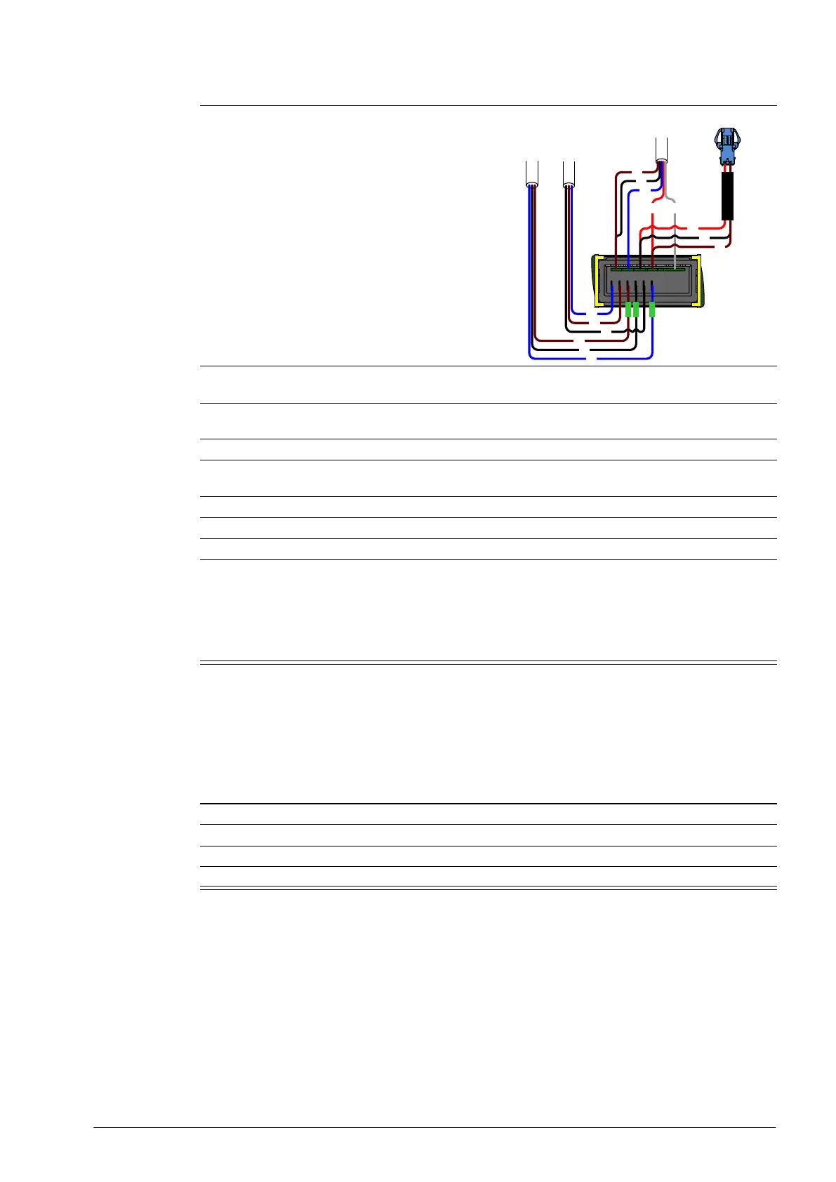
Procedure 36: To replace the controller (continued)
BK
BU
BN
BK
BU
BN
BK
BN
RD
WH
BU
RD
BK
BN
Controller
Flex 1 (red)
Controller
Flex 2 (blue)
Controller
Signal Flex (6-Way)
Procedure 37: To replace a door switch
1. Disconnect the cabinet from the mains power supply (see page 22).
2. Disconnect the door switch cable plug from the inline connector.
3. Unscrew the two fixing screws from the door switch and remove.
4. Fit the replacement door switch and connect via the inline connector.