21
SKOPE BME-N ActiveCore
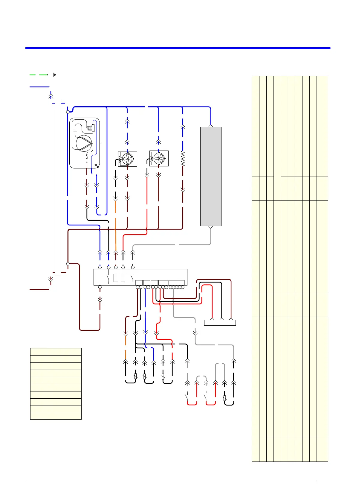
Wiring
Service Manual
5 Wiring
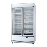
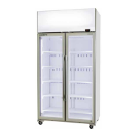
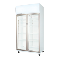
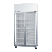
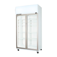
Model: BME600/1200N-A Series
LEGEND
Internal Unit Junction Box Sockets/Plugs S9/P9 Not Used S19/P19 Evaporator Motor Unit Socket/Plug (White 4-way)
Inlet IEC Cabinet Socket/Plug S10/P10 Not Used S20/P20 Condenser Sensor Socket/Plug (Red 2-way)
S1/P1 Not Used S11/P11 Not Used T1 Unit Terminals
S2/P2 Unit Junction Box to Controller Signal Socket/Plug (6-way) S12/P12 Not Used External Sockets/Plugs
S3/P3 Unit Junction Box to Controller Power Socket/Plug (Blue 4-way) S13/P13 Not Used S21/P21 Evaporator Motor Extension Socket/Plug (Red 4-way)
S4/P4 Heater Wire Unit Socket/Plug (Black 3-way) S14/P14 Not Used S22/P22 Ambient Sensor Socket/Plug (White 2-way)
S5/P5 Light Unit Socket/Plug (White 3-way) S15/P15 Compressor Unit Socket/Plug (Blue 4-way) S23/P23 Programming/Comms Port Socket (Blue 4-way)
S6/P6 Unit Junction Box to Controller Power Socket/Plug 1 (Red 4-way) S16/P16 Evaporator Sensor Socket/Plug (Black 2-way) S24/P24 Compressor Electrics Plug
S7/P7 Door Sensor Socket/Plug (White 2-way) S17/P17 Cabinet Sensor Socket/Plug (Blue 2-way) S25/P25 LED Driver DC Output Socket/Plug (Red 2-way)
S8/P8 Not Used S18/P18 Condenser Motor Unit Socket/Plug (Red 4-way) S26/P26
Heater Wire Extension Flex Socket/Plug (Black 3-
way)
S18-2 P18-2
S24-4 P24-4
P6-1 S6-1
P3-1 S3-1
P3-4 S3-4
P6-4 S6-4
BN
BU
BU
Compressor
RS
C
L
N
Start
Relay
Compressor
Overload
S24-3 P24-3
BN
BU
BN
S21-4 P21-4
S21-2 P21-2
Condenser Fan
BN
S18-4 P18-4
Evaporator Fan
BU
BU
BU
S2-1 P2-1
S2-2 P2-2
S2-3 P2-3
S2-5 P2-5
BK
BK
OG
BK
BK
BK
BK
BK
Cabinet
Probe
Evaporator
Probe
BN
Inlet-L
Inlet-N
BN
BU
T1-2
GNYE
EMC Filter
BU
BN
P17-2 S17-2
S6-2 P6-2
BU
P4-1 S4-1
Pillar elements
WDTL
SCS
Controller
L N
C
R
R
SSR
S1
S2
SSR
Comp.
0V
+
1
2
3
AD5
DI1
0V
AD1
DI2
0V
AD2
DI3
0V
AD3
DI4
5V
0V
AD4
BK
BK
BN
BU
P3-2 S3-2
S19-2 P19-2
S19-4 P19-4
BN
BK
T1-1
BK
RD
BN
WH
S4-2 P4-2
BN
BN
P18-1 S18-1
BU
BU
P21-1 S21-1
P19-1 S19-1
BU
BN
WH
WH
RD
Door Switch
WH
WH
RD
Door Switch
BK
BK
Condenser
Probe
P17-1 S17-1
P16-1 S16-1
P16-2 S16-2
P20-2 S20-2
P20-1 S20-1
S23-4
S23-1
S23-3
P22-2 S22-2
BK
BK
P22-2 S22-2
BK
P7-2 S7-2
S2-4 P2-4
RD
BU
BU
WH
P7-1 S7-1
WH
BK
WH
RD
mbient
Probe
RD
BK
Programming
BN
BN
BK
P5-1 S5-1
S5-2 P5-2
BU
Ledtech Lighting
BU
BN
BK
BK
OG
S15-1 P15-1
S15-2 P15-2
BU
BN
WIRE COLOURS
BK Black
BN Brown
RD Red
OG Orange
GN Green
BU Blue
GY Grey
WH White
GNYE Green-Yellow
Based upon IEC 757 Standard