connect S.Port wire from receiver to Tel pin next to SBus input.
Channels assignments should normally be as following:
Input channel 1 – Roll
Input channel 2 – Pitch
Input channel 3 – Throttle
Input channel 4 – Yaw
Input channel 5 – Mode selection
Input channel 6 – RTH Mode
Input channel 7 – Auto Mode
Modes can be remapped in Configurator software later.
RSSI Monitoring
If you want the flight controller to read the information about RSSI (Received Signal Strength Indicator) from RC receiver - simply connect the
RSSI output and GND from your RC receiver to PWM I/0 #13 of the flight controller. RSSI information will appear in the GCS and also on OSD
screen.
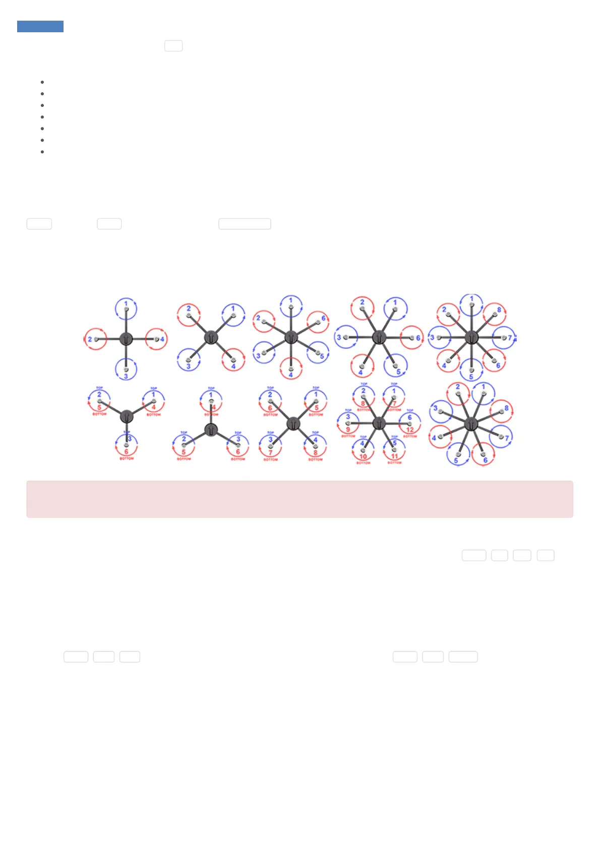
Motors ESC
Connect ESC inputs to SmartAP PWM outputs 1-12. The first motor is always front or front-right, it’s spinning direction is CCW.
Be sure NOT to mix up polarity!
GND line (black) is near edge, +5V line (red) in the middle, Signal line (yellow) is upper row.
Telemetry module
Connect telemetry antenna to telemetry antenna port. If you would like to use external telemetry module - connect GND , 5V , RX , TX pins
of the Telemetry port to external telemetry module. Later, you will need to disable onboard telemetry module SmartAP GCS Configurator
software.
OSD Video
SmartAP has integrated OSD (On-Screen display) module. It means that you can connect your camera output to the autopilot (instead of direct
connection to the video transmitter) and then connect the Video Output of the flight controller to the video transmitter. In this case, the autopilot will
overlay the flight information (mode, altitude, speed, battery status and etc.) on the screen. Connect the video camera to Video IN port of the
autopilot ( GND , 12V , VIN ). Connect the video transmitter to Video OUT port of the autopilot ( GND , 12V , VOUT ).