- 54 -
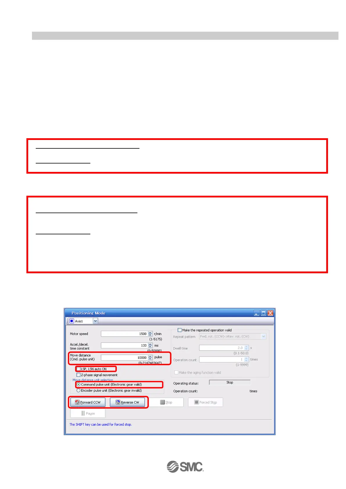
5.6.4 Move distance Configuration and Operation< Move distance Configuration>
< Move distance Configuration>
① Set the move distance [pulse]. Select a value within the stroke range.
② Actuator position will operate using [Forward (CCW)], [Reverse (CW)].
The position at which power is turned ON will be set as the home position, and the actuator will travel the amount
set as move distance (check wiring and parameters If operation is not performed correctly).
When performing positioning operation in the setup software, the rotation direction of the actuator does not
change if you change the setting of parameter PA14 (Rotation direction selection). The actuator moves in the
direction of [Forward (CCW)] button and [Reverse (CW)] button.
③ Check command input pulse units (electronic gear enabled).
The electronic gear duty configured in PA05/PA06/PA07 will be enabled. See “LECSA Operation Manual
(Simplified Edition)”,section 5.3.4 for setting values for PA05/PA06/PA07 in each actuator. If parameters
PA05/PA06/PA07 are set according to“LECSA Operation Manual (Simplified Edition)”,section 5.3.4, the travel
distance of the actuator per 1 pulse will be as follows.
【Position control mode (pulse input)】
・ travel distance of the actuator per 1 pulse = 10[μm] ( 0.01[mm])
【Positioning mode】
・ travel distance of the actuator per 1 pulse = 1[μm] ( 0.001[mm])
Travel distance (mm) must be converted to tavel distance (pulse).
See below for the conversion formula.
As an example, for a travel of 100mm;
【Position control mode (pulse input】
Travel distance of the actuator per 1 pulse = 0.01 (mm)
*1
100 (mm)/0.01 (mm) = 10000 (pulse)
【Positioning mode】
Travel distance of the actuator per 1 pulse = 0.001 (mm)
*1
100 (mm)/0.001 (mm) = 100000 (pulse)
*1 The travel distance of the actuator per 1 pulse is set according to the electronic gears (PA05/PA06/PA07) outlined in “LECSA Operation
Manual (Simplified Edition)”,section 5.3.4 “Recommended Parameter Values by Actuator Model”.
④ If the stroke end signals (LSP, LSN) are not turned ON, an alarm may occur (If checked, the stroke end (LSP,
LSN) signals will be turned ON automatically only when this window is open).
* Ensure that the [Forward (CCW)] and [Reverse (CW)] driving directions are checked. If the driving direction is
unclear, operate the actuator slowly with a small move distance while checking the driving direction.
 Loading...