- 61 -
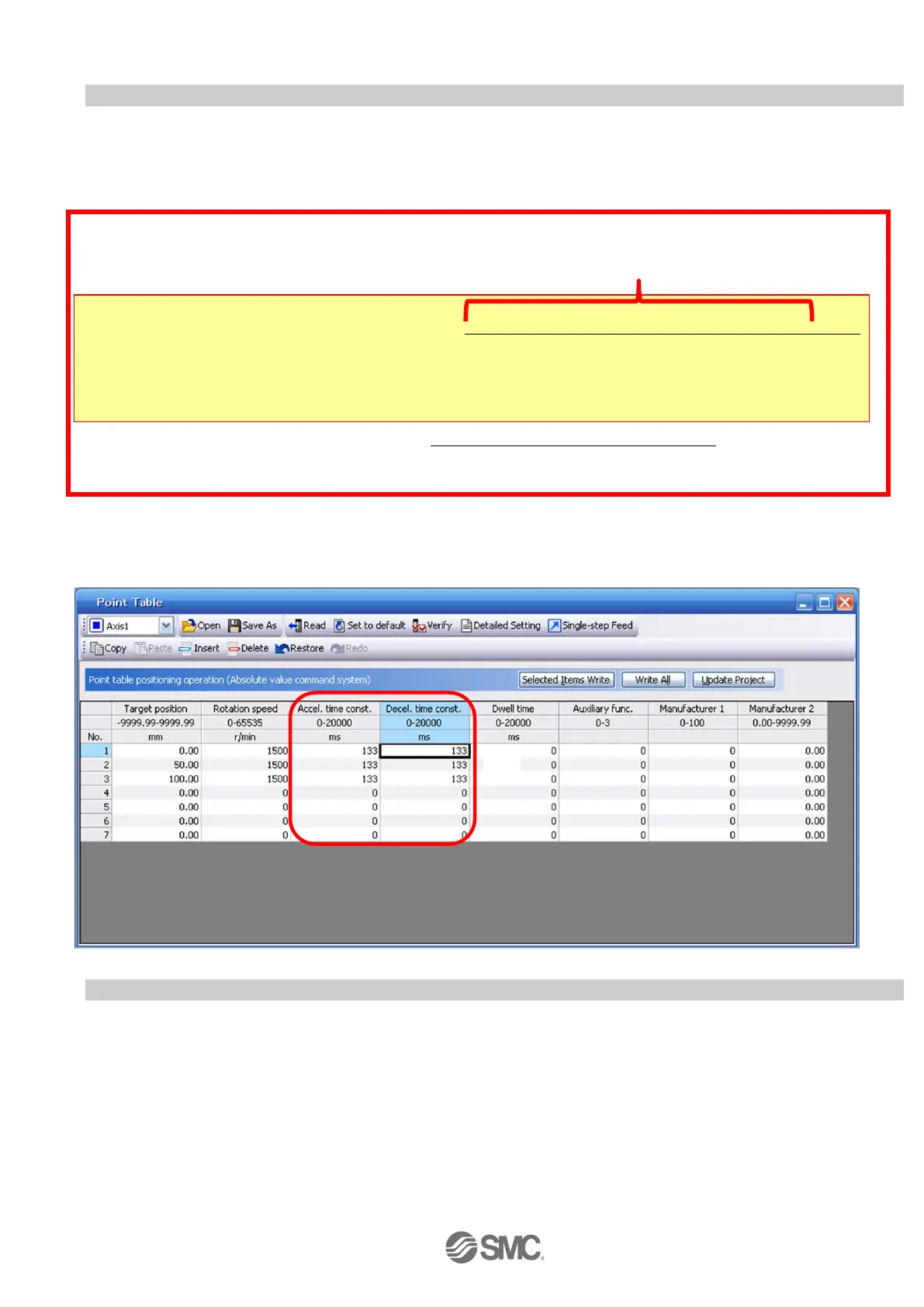
5.7.5 Point Table (Acceleration time constant/Deceleration time constant) Configuration
< Acceleration time constant/Deceleration time constant Configuration>
① Acceleration time constant (ms)/Deceleration time constant (ms) configuration:
Acceleration/deceleration (mm/s
2
) must be converted to the acceleration time constant/deceleration time constant (ms).
See below for the conversion formula.
Conversion example for a 8[mm] lead actuator driven at an acceleration of 3000 [mm/sec
2
]
Acceleration/Deceleration time constant (ms) = {3000 (r/min) ÷60 (S) } × 8 (mm) × 1000
3000 (mm/s
2
)
= 133 (ms)
The acceleration time constant/deceleration time constant defines the time in (ms) when the motor rotations of
(3000[r/min]) are met.
The acceleration time constant/deceleration time constant must be a number between 0 and the allowable
acceleration/deceleration speed range for each actuator.
5.7.6 Other Settings
The dwell and auxiliary functions are set to 0 as default.
Do not change Manuf .1 (0) or Manuf .2 (0.00) from the initial values.
Acceleration time constant/deceleration time constant (ms) = {Rated rotation speed (r/min) ÷60 (S) } x screw lead (mm) x 1000
Acceleration/deceleration speed (mm/s
2
)
*As the scceleration time constant/deceleration time constant units are in ms; this is calculated as (s) ×1000
 Loading...