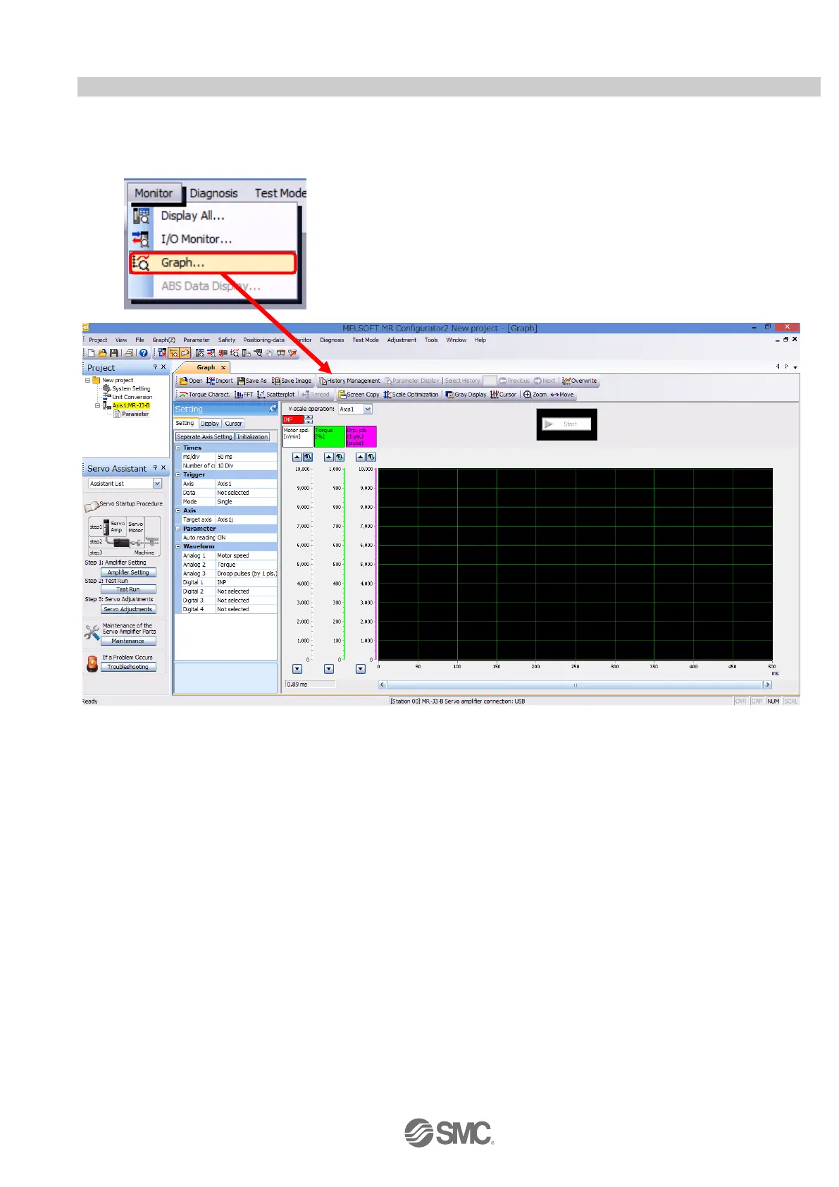
Home
SMC Networks
Servo Drives
LECSA Series
SMC Networks LECSA Series User Manual
4
of 1
of 1 rating
96 pages
Give review
Manual
Specs
To Next Page
To Next Page
To Previous Page
To Previous Page
Loading...
-
69
-
5.1
1 A
cquisition of motion w
aveform with graph monitor
W
ith
the
setup
s
oftware
(MR
Configurator2
TM
:
LEC-
MRC2E)
monitor
graph
f
unction,
the
m
otion
wa
veform
during
electric actuator oper
ation can be obtained as
desc
ribed below
.
①
Click “Monitor”
-
“Graph” of
Setup software to displa
y “
G
raph
”
window
.
①
70
72
Table of Contents
Table of Contents
3
Contents
3
Introduction
8
Terms
8
Configuration
8
Pre-Operation Procedure
9
Flow Chart
9
Wiring
10
Power Supply Wiring
10
I/O Signal Connection Example
11
Position Control Mode (Sink I/O Interfaces)
11
Speed Control Mode (Sink I/O Interfaces)
14
Torque Control Mode (Sink I/O Interfaces)
15
Positioning Mode (Sink I/O Interfaces)
16
Source I/O Interfaces
17
List of Parameters for each Mode
18
Parameters Common to each Mode
18
Position Control Mode
18
Speed Control Mode
19
Torque Control Mode
19
Positioning Mode
20
Parameter Configuration Using Setup Software (MR Configurator2 )
21
PC Setup Software
21
Installation Method
21
Basic Driver Set-Up for Initial Test Drive
21
Start up the Setup Software
22
System Settings
23
Model Selection
23
Driver on LINE Check
24
Help Function
24
Parameter Setting (Driver Side)
25
Change of Parameter Block
26
Read of Parameters
26
Parameter Configuration Method (Ex. "Control Mode" Selection)
27
Recommended Parameter Values by Actuator Model
28
Electronic Gears
33
Control Mode Selection
34
Set the Parameter of Command Pulse Input Form
35
Verify of Parameters
37
Parameter Initialization
38
JOG Mode in the Setup Software
39
JOG Mode
40
Changing I/O Signal Allocation
41
Automatic Input Signal on Selection Parameter Configuration
41
Initial I/O Signal Allocation
43
Signal Allocation Using Setup Software
44
Allocation Examples for Position Control Mode (Pulse Input)
45
Setting a Maximum of 7 Points Using the Point Table in Positioning Mode (Point Table)
47
I/O Signal Allocation Check
51
Positioning Mode in Setup Software
52
Positioning Mode
53
Motorspeed Configuration
54
Acceleration/Deceleration Time Configuation
55
Move Distance Configuration and Operation< Move Distance Configuration
56
Positioning (Point Table) Operation Using the Setup Software
57
Point Table List
57
Point Table Data
58
Point Table (Target Position) Configuration
59
Point Table (Rotation Speed) Configuration
62
Point Table (Acceleration Time Constant/Deceleration Time Constant) Configuration
63
Other Settings
63
Single-Step Feed
64
Saving/Loading Parameters
65
Saving Parameters
65
To Load Saved Parameters
66
Saving/Loading Project
67
Saving Project
67
To Load Saved Project
68
Saving/Loading Point Table
69
Saving Point Table
69
To Load Saved Point Table
70
Acquisition of Motion Waveform with Graph Monitor
71
Under the Setting Tab: Setting of the Items to Display the Graph
72
Trigger Wait
76
Operation Instruction
77
Saving of Waveform
78
Display All Monitor List
79
Home Position Return Method
81
Position Control Mode (Pulse Input)
81
Positioning Mode (Point Table)
81
Stopper Type Home Position Return
82
Diriving Methods for each Mode
84
Position Control Mode (Pulse Input)
84
Position Control Mode Instructions
84
Speed Control Mode
85
Speed Control Mode Operation Instruction
85
Torque Control Mode
86
Torque Control Mode Operation Instruction
86
Positioning Mode (Point Table Method)
87
Operation Instruction of Point Table System
87
Setting Method
89
Positioning Mode (Programimg Method)
90
Setting Method
90
Command in the Program System
91
Operation Instruction Method of Program System
92
4
Based on 1 rating
Ask a question
Give review
Questions and Answers:
Need help?
Do you have a question about the SMC Networks LECSA Series and is the answer not in the manual?
Ask a question
SMC Networks LECSA Series Specifications
General
Brand
SMC Networks
Model
LECSA Series
Category
Servo Drives
Language
English