Sirius 800 www.snellgroup.com Door PC Maintenance
Issue 1 Rev 1 Page 84 © 2014 Snell Limited
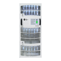
3. Support the Door PC and remove the 8 screws that fix the Door PC to the router door
(see Fig 44.). Keep the screws, the spade connector and plastic cable clip for when
the new Door PC is fitted.
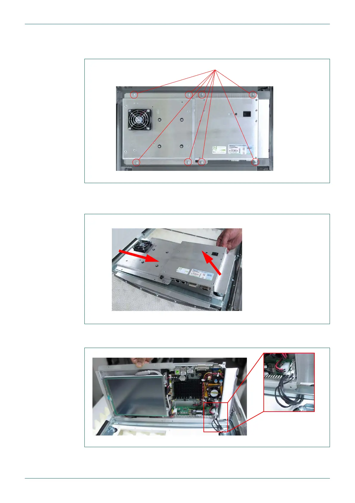
4. Pull the right side of the Door PC away from the router door and then slide the Door
PC to the right slightly to expose the final wires still connected to the Door PC power
supply (see Fig 45. and Fig 46.).
5. The LEDs in the router door are powered from the Door PC power supply board
(see Fig 46.). Remove the plugs from the Door PC PSU.
6. Put the old Door PC to one side.
Fig 44. 8 x Door PC Fixing Screws
Fig 45. Door PC Removal
Fig 46. Door LED Connections
8 x M3 x 10 mm Pozidriv Screws
2) Slide the Door PC to the right to remove it
1) Pull the right side
of the Door PC away
from the router door
1
2
Door PC PSU LED
Connectors