Sirius 800 www.snellgroup.com Door PC Maintenance
Issue 1 Rev 1 Page 85 © 2014 Snell Limited
7. Pick up the new Door PC and reconnect the door LED plugs to the Door PC PSU
connectors (see Fig 46.).
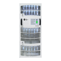
8. When installing the Door PC locate the left edge of the Door PC assembly first and
then push the right edge of the Door PC towards the router door (see Fig 47.).
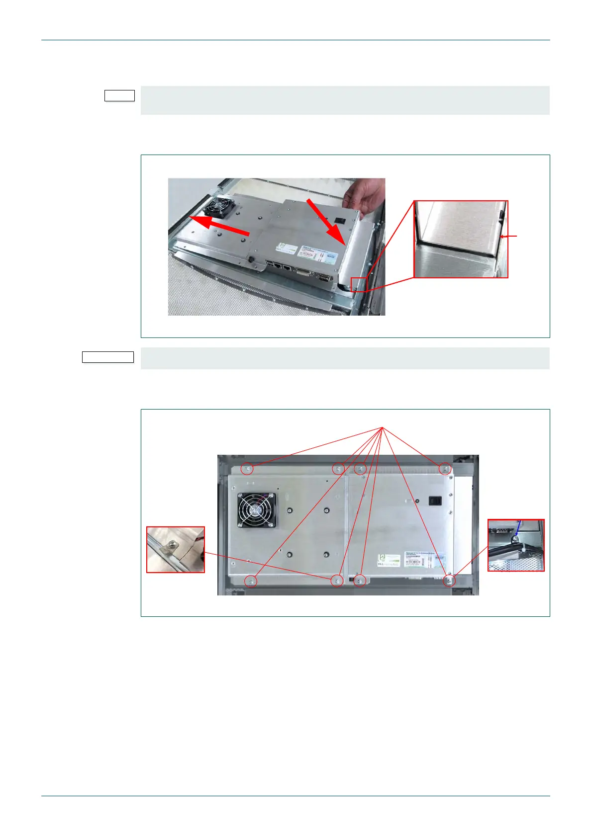
9. Refit the 8 x M3 x 10 mm screws (see Fig 48.). Make sure the spade connector and
plastic cable clip are fitted.
It doesn’t matter which connector is used for which door LED plug as the outputs are all the
same.
Fig 47. Door PC Installation
Ensure that the right edge of the Door PC fits inside the router door (see Fig 47.).
Fig 48. Refit the Door PC Fixing Screws
1) Locate the left edge of the Door PC first
2) Push the right side of the
Door PC towards the router
door
2
1
3) Make sure the right edge
of the Door PC fits inside the
door frame
3
8 x M3 x 10 mm Pozidriv Screws
Spade
Connector
Plastic Cable
Clip