ATyS C55/65
549782D
QUICK START GUIDE
1
2
201 202
101 102
312313 314315 316317 63A64A 24 14 04 13
11 14 12 21 24 22 31 34 32 41 44 42 51 54 52 61 64 62
71 72 73 74 75 76 70 82 81
L1
L2
L3
N
L1
L2
L3
N
230/400 V 230/400 V
OUT 1 OUT 2 OUT 3 OUT 4 OUT 5 OUT 6
USB
CT
IN1 IN2 IN3 IN4 IN5 IN6
COM
RS485SOURCE 1
1A type gG 1A type gG
4A
type
gG
4A
type
gG
CTR
ATyS
AVAL
OFF II I0C
II I0C
DIGIWARE
DIGIWARE
INPUTS
SOURCE 2
NC
-+
L1 L2 L3 NL1L2L3N I1 I2 I3 IN GNDGND
Aux. 1
Aux. 2
IEC 61010
Non contractual document.
Subject to change without notice.
Preliminary operations
Check the following upon delivery and after
removal of thepackaging:
• Packaging and contents are in good condition.
• The product reference corresponds to the order.
• Contents should include:
Qty 1x C55 or C65 Controller
Qty 1x Controller IP65 gasket (C65 only)
Qty 4x Door mounting screws
Qty 1x Connector kit
Qty 4x Backplate mounting feet
Warning
Risk of electrocution, burns or injury to
persons and / ordamage to equipment.
This Quick Start is intended for personnel
trained in theinstallation and commissioning
of this product. For further details refer to the
product instruction manual available onthe
SOCOMEC website.
• This product must always be installed and
commissioned by qualied and approved
personnel.
• Maintenance and servicing operations should
be performed by trained and authorized
personnel.
• Do not handle any control or power cables
connected tothe product when voltage may
be, or may become present on the product,
directly through the mains or indirectly through
external circuits.
• Always use an appropriate voltage detection
device toconrm the absence of voltage.
• Ensure that no metal objects are allowed to fall
in thecabinet (risk of electrical arcing).
Failure to observe good engineering practices
as well as tofollow these safety instructions may
expose the user and others to serious injury or
death.
Risk of damaging the device
In case the product is dropped or damaged
in any way itis recommended to replace the
complete product.
Installation standards must be respected.
Accessories
• Digiware I/O 10 (ref. 48290140)
• Gateway M70 (ref. 48290222)
• Controller 24 VDC aux power supply
(6W minimum type SELV) mandatory with I/0
10 Modules
For further details refer to the product instruction
manual under chapter “Spares and Accessories”
Spares
• Connector kit (ref. 16090002)
• Controller backplate mounting feet
(ref. 16090005)
• Controller door mounting screws
(ref. 16090004)
• Controller IP65 gasket (ref. 16090001) (C55/65)
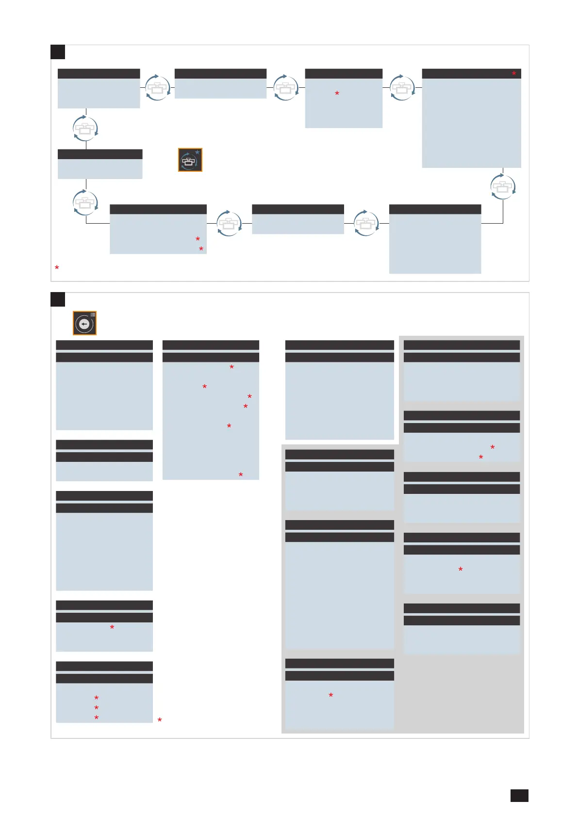
set as favorite.
(1) Maintenance alarms must be congured for this menu to show any values.
- Short press on this button to go back one level.
- Long press to access the menus.
MAINTEN. ALARMS
 Loading...